12
revolution
Revolution Education Ltd. Web: www.picaxe.co.uk
Version 2.0 12/10
AXE110.PMD
PICAXE DATALOGGER
9) Using the AXE111 Memory Expansion Board
The optional memory expansion board (part AXE111) allows 7 additional EEPROM
chips (e.g. 24LC256) to be connected to the AXE110 Datalogger to increase its
memory capacity from 1 EEPROM to 8 EEPROMs.
Kit Contents/ Assembly:
PCB
PCB
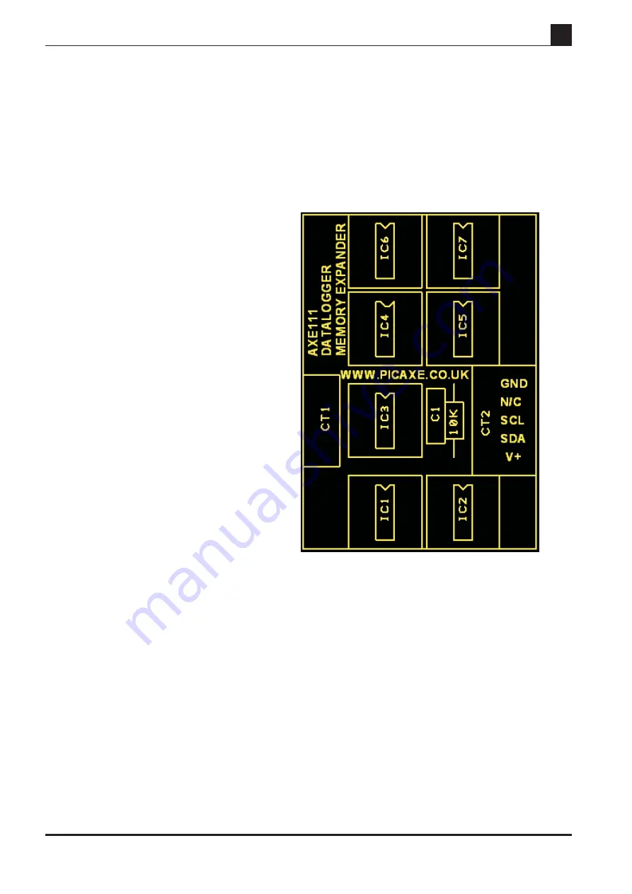
IC1-7 8 pin IC sockets (x7)
C1
100nF capacitor
R1
10k resistor
CT1
5 pin r/a header
CT2
5 pin r/a socket
All parts should be soldered in position as shown
in the diagram above. Note that the kit does not
include EEPROM chips which must be purchase
separately (e.g. 24LC256, part MIC050).
Slave Address
The PCB is arranged to give each memory IC a
unique slave address as follows. (Note that the IC
with address %10100000 is fitted on the AXE110
datalogger board).
IC1
%10100010
IC2
%10100100
IC3
%10100110
IC4
%10101000
IC5
%10101010
IC6
%10101100
IC7
%10101110
Write Enable
The Write Enable pin of each EEPROM is tied low by the 10k resistor, and so by
default is permanently enabled. However, if desired, this can be controlled by
output6 of the PICAXE microcontroller on the datalogger module.
To use this option a wire link must be soldered between the two pads marked LK1
on the solder side of the AXE110 Datalogger. This connects output6 to the
connector. Note that this option cannot be used if output6 is already being used to
drive a serial LCD module.
10) Using the SPE030 Speech Module ( discontinued) .
The optional SPE030 speech module can be used to speak datalogging readings as
they are taken. This module uses the i2c bus. To use this module insert the bottom
5 pins (i2c and power) of the SPE030 PL1 connector into the AXE110 i2c connector
(CT8). See the SPE030 datasheet for more information on how to use this module.


