7
revolution
Revolution Education Ltd. Web: www.picaxe.co.uk
Version 2.0 12/10
AXE110.PMD
PICAXE DATALOGGER
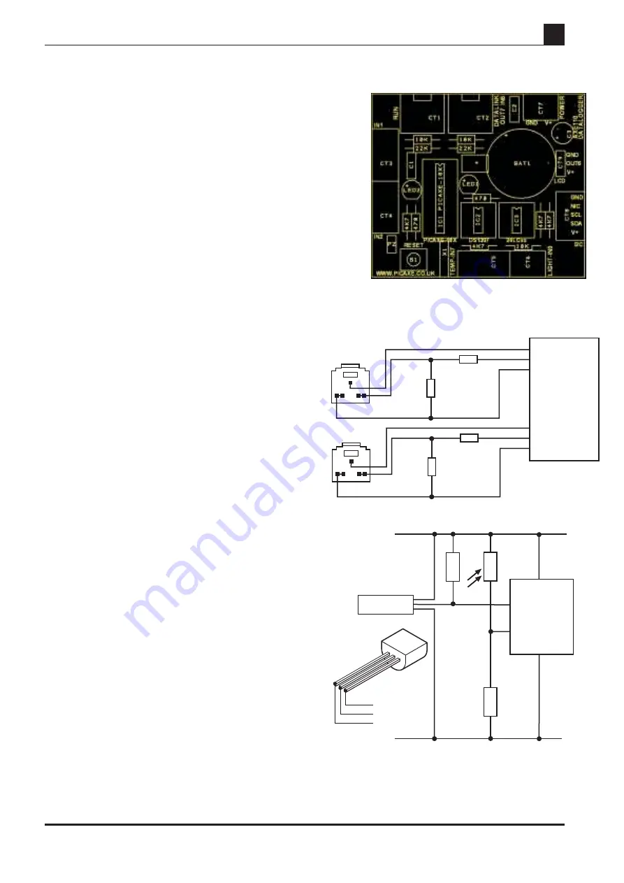
4) PICAXE Datalogger Input/ Output Pin Connections:
Analogue Input 0
- LDR light sensor (connector CT6)
Analogue Input 1
- spare sensor input 1 (CT3)
Analogue Input 2
- spare sensor input 2 (CT4)
Digital Input 6
- datalink serial input
Digital Input 7
- DS18B20 temp. sensor (CT5)
Output 0
- piezo sounder (optional - PZ)
Output 1
- i2c SDA
Output 2
- bicolour LED red
Output 3
- bicolour LED green
Output 4
- i2c SCL
Output 5
- EEPROM Write Enable
Output 6
- serial LCD (optional - LCD)
Output 7
- datalink serial output
Serial Connection
The PICAXE download ‘run’ connection uses ther standrad
PICAXE programming pins.
The datalink connection uses input 6 for ‘serin’ serial
commands and output 7 for ‘serout’ serial commands.
Default Sensors
The datalogger is supplied with two sensors, and has
capacity for an additional 2 sensors (not supplied). Note
the power connections and inputs are labelled on the
solder side of the PCB.
LDR
A miniature LDR (light dependant resistor) can be
connected into terminal block CT6, so that it is connected
to input0 of the PICAXE microcontroller.
The light level can then be measured by use of the ‘readadc’
command.
DS18B20 Digital temperature Sensor
The DS18B20 digital temperature sensor can be connected
into terminal block CT5, so that it is connected to input7 of
the PICAXE microcontroller. The flat side of the sensor
should face down as it is connected into the terminal block.
The digital temperature sensor is a very accurate device
which will give readings in exact degrees celsius by use of
the ‘readtemp’ command.
V+
Input1
0V
V+
Input2
0V
0V
Input7
V+
Input0
V+
DS18B20
4.5V
0V
PICAXE
temperature
sensor
4k7
V+
0V
input
pin7
V+
data
0V
10k
LDR
input
pin0
x
x
x
x
x
22k
10k
Run CT1
x
x
x
x
x
22k
10k
Datalink CT2
serial out
serial in
0V
PICAXE
output 7
input 6
0V


