・
Always perform contour cutting on level ground and in a
stable position. If contour cutting is done with the machine
tilted or in an unstable position, the frame may topple
during operation, resulting in accident or injury.
.
・
Do not wear gloves while operating the unit. T hey may
become caught in the moving parts, leading to accident
or injury.
・
Do not perform contour cutting on round workpieces.
The workpiece may turn during the cutting operation,
resulting in accident or injury.
・
When performing contour cutting, make sure the
workpiece is supported securely with both ends of the
workpiece at least 10cm from the blade. If the workpiece
is too close, it may get caught in the blade, resulting in
accident or injury.
WARNING
1. Contour Cutting
(Figs. 32 - 34)
Other Uses
This tool can be used for contour cutting. Use the following
procedure to perform contour cutting, while observing the
warnings noted below
.
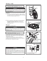
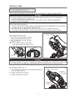
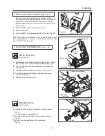
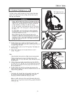
(1) Pull the stopper pin ring to the left of the motor, while
simultaneously grasping the handle and lifting the frame so it
is vertical. (Figs. 32 & 33)
(2) Set the ON/OFF switch to the "ON" position. The blade will
start rotating.
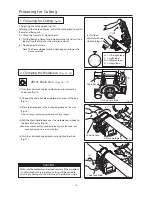
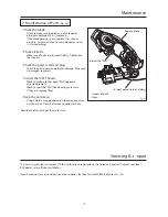
( 3) Place the workpiece on a contour table and cut it
slowly. ( F ig. 34)
Notes:
・
Cut particularly slowly when cutting inward or downward.
・
When cutting downward, press the blade against the
workpiece with less force and make sure your body does not
lunge forward.
(4) When cutting is complete, immediately turn the ON/OFF
switch to the "OFF" position. If you are not going to continue
to use the unit, remove the power plug from the outlet as a
fail-safe procedure.
(5) Pull the stopper pin, while simultaneously grasping the
handle and lowering the frame.
This will return the unit to the
normal cutting position.
Notes:
・
The blade is for straight line cutting only
. It cannot be used
for curved cutting. Forcing the blade to cut in a curve
may chip it or make it able to cut only in a curve.
・
Blades used for contour cutting tend to become able to cut
only in a curve. To perform normal cutting, replace the blade
with a new one.
Pull stopper pin and
simultaneously turn 90
°
Fig. 32
Fig. 33
Fig. 34
Stopper pin
Contour table
Workpiece
- 15 -
Summary of Contents for MANTIS 120A
Page 23: ...XB125 120 E4 0802R0200 S S ...


