DEM Page 32 of 43 FEBRUARY 07
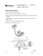
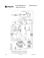
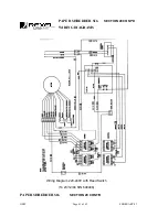
The sensor is mounted on the printed circuit board (PCB) (fig 11b) and detects the high
current drawn when the motor stalls due to the cutting head jamming. The magnetic field of
the wire passing through the coil is sensed by the coil and operates the potentiometer, which
forms part of the logic circuit controlling the contactors which switch the motor.
When jamming occurs, after a short pause, the motor will automatically reverse momentarily
and then stop; the unshredded paper having been returned to the feed chute. The
illuminated controls will now indicate the “STOP” mode. Manual reverse can be obtained by
pressing the reverse button on the control panel to give momentary reverse and then stop.
The waste container door is linked to a safety switch which is connected in the logic circuit
and when open also reverts the machine to the “STOP” mode. This condition is indicated by
an illuminated on the switch control panel.
A “Fail-Safe” circuit is incorporated within the logic circuit, to detect any interruption in the
power supply that may cause the machine to suddenly cease working. When the power
supply is restored the machine will automatically be reset into the “STOP” mode.
Machine Not Cutting the Required Number of Sheets
Each machine is set at the factory to achieve the cutting of the maximum number of sheets.
The electrical control is achieved by setting the potentiometer on the PCB (fig 11b). The
electrical setting is checked using the 2-pin test plug located by the potentiometer and
checking the electrical resistance (ohms); compare the value with the factory setting value.
N.B. The setting screw located on the top of the potentiometer is used to achieve adjustment
if necessary. Turning the screw clockwise will increase the maximum number of sheets cut.
Should any other problems be encountered with the electronics, the complete PCB should be
replaced.
PAPER SHREDDER S16 SECTION 14
SERVICE INSTRUCTIONS
Summary of Contents for S16
Page 21: ...DEM Page 21 of 43 FEBRUARY 07 ...


