background image

Rexnord Industries, LLC 3001 W. Canal St., Milwaukee, WI 53208-4200 USA

378-200

 (PN-2128394)

 Telephone: 414-342-3131 Fax: 414-937-4359

November 2010

 e-mail: info@rexnord.com web: www.rexnord.com

Supersedes 6-07

Owners Manual 

 Falk™ Quadrive Shaft Mounted Drives Model A

(Page 16 of 44)

Sizes 5107-5315

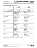
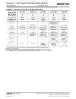
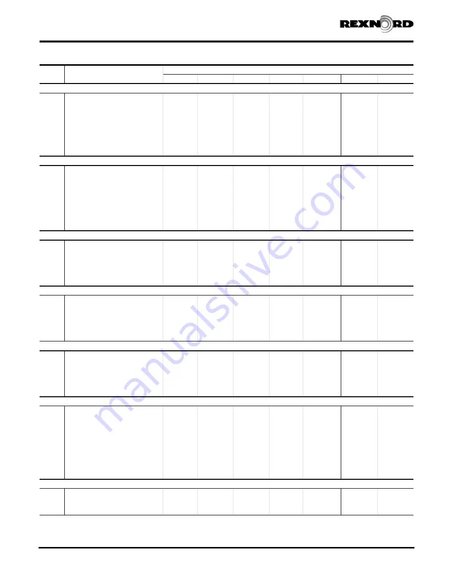
TABLE 11 — Parts List of Falk Part Numbers

Ref.

No.

Part Description

DRIVE SIZE

5107 

H

5115 

H

5203 

H

5207

5215

5307

5315

Housing Components

13

Shaft Cover-LS

2109906

1164350

1164353

2110134

1164359

2110504

2110779

15

Seal Cover

4723094

4723095

4723096

4723097

4723098

4723099

4723109

16

Shaft Cover

1161865

1161866

1238030

2119130

1161870

1161870

1161870 

l

16

Shaft Cover W/ BKSP

1243290

1161866

1238019

2119130

1219342

1237944

1219342

17

Cover Spacer BKSP

1243292

1243296

2119132

19

Seal, 

2916797

2921425

2921422

2921421

2904606

2921423

2922295

20

Seal, HS

2921419

2921416

2902929

2921417

2921420

2916797

2920669

30

Air Vent

0914088

0914088

0914088

0914088

0914088

0914088

0914088

80

Fastener Kit

4729000

4729000

4729032

4729049

4729064

4729082

4729100

100

Shim & Gasket Kit

4729429

4729430

0786836

0786837

0786838

0786839

0786840

Rotating Elements — J05

3A

Shaft Ass'y-Inc 3A1-3A4

4729363

4729377

4729045

4729061

4729076

4729094

4729112

3A1

Bearing

2926357

2926361

2919339

2918700

2919359

0921354

2919215

3A2

Bearing

2926357

2919340

2919340

0921521

2919360

2916263

0921853

3A3

Pinion & Shaft-Inc 3A4

4729364

4729378

4729046

4729062

4729077

4729095

4729113

4A

Shaft Ass'y-Inc 4A1-4A5

4729365

4729033

4729047

4729063

4729078

4729096

4729114

4A1

Bearing

4729014

4720891

2911822

2905191

0921778

0921727

0921366

4A2

Bearing

4729014

4720891

2911822

2905191

0921778

0921727

0921366

4A3

Hollow Shaft w 4A5 Key

4729016

4723015

4723028

4723039

4723050

4723061

4723073

4A4

Gear

1242585

1238105

1242878

1237897

1242848

1242860

1237763

5A

Backstop Ass'y

0795654

0793995

0785596

0783905

0785610

Rotating Elements — J09

1A

Shaft Ass'y W/O 1A4 Gear

4729366

4729380

4729037

4729053

4729068

4729086

4729104

1A

Shaft Ass'y With 1A4 Gear

4729367

4729381

4729034

4729050

4729065

4729083

4729101

1A1

Bearing

2926357

2926361

2919339

2918700

2919359

0921354

2919215

1A2

Bearing

2926357

2919340

2919340

0921521

2919360

2916263

0921851

1A3

Pinion & Shaft w 1A5 Key

4729368

4729382

4729041

4729056

4729071

4729089

4729107

1A4

Gear

1242532

1242536

1242834

1242842

1242849

1242857

1242861

5A

Backstop Ass'y

0795654

0793995

0785596

0783905

0785610

0785529

0757183

Rotating Elements — J14

1A

Shaft Ass'y W/O 1A4 Gear

4729369

4729383

4729038

4729054

4729069

4729087

4729105

1A

Shaft Ass'y With 1A4 Gear

4729370

4729384

4729035

4729051

4729066

4729084

4729102

1A1

Bearing

2926357

2926361

2919339

2918700

2919359

0921354

2919215

1A2

Bearing

2926357

2919340

2919340

0921521

2919360

2916263

0921851

1A3

Pinion & Shaft w 1A5 Key

4729371

4729385

4729042

4729057

4729072

4729090

4729108

1A4

Gear

1242533

1242537

1242833

1242843

1242850

1242858

1237856

1A5

Backstop Ass'y

0795654

0793995

0785596

0783905

0785610

0785529

0757183

Rotating Elements — J25

1A

Shaft Ass'y W/O 1A4 Gear

4729372

4729386

4729039

4729055

4729070

4729088

4729106

1A

Shaft Ass'y With 1A4 Gear

4729373

4729387

4729036

4729052

4729067

4729085

4729103

1A1

Bearing

2926357

2926361

2919339

2918700

2919359

0921354

2919215

1A2

Bearing

2926358

2926359

2919340

0921521

2919360

2916263

0921853

1A3

Pinion & Shaft w 1A5 Key

4729374

4729388

4729043

4729058

4729073

4729091

4729109

1A4

Gear

1242534

1238106

1238017

1242844

1242851

1242859

1237764

1A5

Backstop Ass'y

0795655

0795658

0785596

0783905

0785610

0785529

0757183

Rotating Elements — J09, J14, & J25

2A

Shaft Ass'y-Inc 2A1-2A6

4729375

4729389

4729040

4729059

4729074

4729092

4729110

2A1

Bearing

2926359

2926360

2919338

2918700

0921350

0921793

0921850

2A2

Bearing

2926359

2926360

2919338

2918701

2916288

0921793

0921850

2A3

Pinion & Shaft w 2A4 Key

4729376

4729390

4729044

4729060

4729075

4729093

4729111

2A5

Spacer

1179876

1179877

2A6

Spacer

1161925

1163034

1161889

1163762

21200246

4A

Shaft Ass'y-Inc 4A1-4A5

4729365

4729033

4729047

4729063

4729078

4729096

4729114

4A1

Bearing

4729014

4720891

2911822

2905191

0921778

0921727

0921366

4A2

Bearing

4729014

4720891

2911822

2905191

0921778

0921727

0921366

4A3

Hollow Shaft w 4A5 Key

4729016

4723015

4723028

4723039

4723050

4723061

4729115

4A4

Gear

1242585

1238105

1242878

1237897

1242848

1242860

1237763

Shaft Fan Assembly — All Ratios

6A

Shaft Fan Ass'y Inc 6A1-6A4

. . .

. . .

. . .

. . .

0785611

0785530

0785432

6A1

Fan

. . .

. . .

. . .

. . .

4729079

4729097

4729116

6A3

Guard

. . .

. . .

. . .

. . .

4729080

4729098

4729117

6A4

Backplate

. . .

. . .

. . .

. . .

4729081

4729099

4729118

H

For Sizes 5107J – 5203J, 4000J/5000J revolving parts not necessarily interchangeable. Consult Service Parts Department.

l

For Size 5315J05 only, use P/N 1161869

Summary of Contents for Falk A

Page 1: ...r Mount Installation 31 Appendix E Vertical Standpipe Installation 33 Appendix F Modifications for Non Standard Mounting Positions 34 Appendix G Retaining Rings for Bushing Nuts and Thrust Plates Tooth Combinations for Vibration Analysis JSC Lip Seal Accessory 36 Appendix H Drive Shaft Recommendations for Tapered Drive Shafts 37 Appendix J Drive Shaft Recommendations Using TA Taper Bushing 38 Appe...

Page 2: ...ive housing or accessories without prior approval from Rexnord Geared Products Welding on the drive may cause distortion of the housing or damage to the bearings and gear teeth Welding without prior approval will void the warranty DRIVE RATING Operate the drive only within the horsepower and output speed for which it was selected and specified in Selection Guide 371 110 for the application Refer t...

Page 3: ...14 937 4359 November 2010 e mail info rexnord com web www rexnord com Supersedes 6 07 Falk Quadrive Shaft Mounted Drives Model A Owners Manual Sizes 5107 5315 Page 3 of 44 5 107 J 25 A Size Series Maximum Bushing Bore 1 7 16 Drive Type Ratio Nominal 25 1 Model Basic J JR Shaft Mounted Drive 1 Basic Drive 2 Torque Arm 3 TA Taper Bushing JSC Screw Conveyor Drive 1 Basic Drive 2 Seal Housing 3 Drive ...

Page 4: ...e 414 342 3131 Fax 414 937 4359 November 2010 e mail info rexnord com web www rexnord com Supersedes 6 07 Owners Manual Falk Quadrive Shaft Mounted Drives Model A Page 4 of 44 Sizes 5107 5315 12 O CLOCK D L F F L D 3 O CLOCK F L D 6 O CLOCK F L D 9 O CLOCK REPOSITION PLUGS TO SUIT REQ D MOUNTING D DRAIN F FILL VENT L OIL LEVEL HIGHEST INPUT SIDE PLUG SIZES 4203 THRU 4315 5 1 RATIO ONLY LOCATE AIR ...

Page 5: ...he value specified in Table 3 Use the seal housing fasteners to secure the seal housing to the basic drive housing Refer to Table 4 for proper torque value Reinstall hollow shaft cover Pack seal housing with waste packing and proceed to Step 5 Rexnord Industries LLC 3001 W Canal St Zip 53208 4200 Milwaukee WI USA PN 2128394 378 200 Telephone 414 342 3131 Fax 414 937 4359 November 2010 e mail info ...

Page 6: ...2128394 Telephone 414 342 3131 Fax 414 937 4359 November 2010 e mail info rexnord com web www rexnord com Supersedes 6 07 Owners Manual Falk Quadrive Shaft Mounted Drives Model A Page 6 of 44 Sizes 5107 5315 TROUGH END TROUGH END MOUNTING FASTENERS WASTE PACKING DRIVE SHAFT TROUGH END GASKET SEAL HOUSING INSERT SEAL HOUSING FASTENERS WITH LOCKWASHERS BASIC DRIVE DRIVE SHAFT KEY HOLLOW SHAFT COVER ...

Page 7: ...2 for 5207 thru 5315 DO NOT remove sling until drive is secured to shaft Before lifting the drive into position rotate the high speed shaft until the hollow shaft keyway will be in position to line up with the driven shaft key JF proceed to Step 12 JSC to Step 13 8 JR If the drive was received with a backstop installed the backstop must be temporarily removed to facilitate mounting Refer to Sectio...

Page 8: ...the thrust plate fastener Refer to Table 3 for torque value Reinstall the hollow shaft cover Install motor mount motor sheaves belts and guard Refer to Appendix D for motor mount installation instructions Proceed to Step 15 13 JSC Assemble drive to trough and install drive shaft Rexnord Industries LLC 3001 W Canal St Milwaukee WI 53208 4200 USA 378 200 PN 2128394 Telephone 414 342 3131 Fax 414 937...

Page 9: ... g foods drugs etc Start Up 18 JR JF JSC Before operating the drive check any fasteners pipe plugs air vent etc which may have been loosened in the course of Outfitting Installing and Lubricating the drive to be sure that they have been properly retightened If a long fastener was used to lift the drive into place reinstall the housing flange fastener and torque to the value shown in Table 1 After ...

Page 10: ...mmediately with pressure sensitive tape Before operating drives which have been stored or inactive remove tape and fill to the proper level with oil meeting specifications given in the Lubrication Recommendation found in Appendix A H Product of the Daubert Chemical Company Chicago Illinois Formerly known as Nucel Oil SHUTDOWN OF NEW OR EXISTING DRIVES WHICH HAVE BEEN OPERATED If a drive is to be s...

Page 11: ...ng the bolt after each blow until separation occurs CAUTION Failure to follow this procedure may result in the destruction of the threads in the thrust plate If the retaining ring becomes damaged refer to Appendix G for replacement information Proceed as follows JF to Step 5 for replacement of Quadrive seals only OR Step 9 for drive disassembly procedure 4 JSC If the drive was removed with the sea...

Page 12: ...ring Grease or magnetize the drill bit to help retain the chips Drill two 125 3 mm diameter holes in the seal case 180 apart Control the angle of the drill as illustrated in Figure 17 to prevent damage to the shaft c Insert two 10 750 M5 x 20 sheet metal screws into the seal case leaving 5 13 mm of the screw protruding above the seal face DO NOT drive the screw more than 25 6 mm beyond seal face o...

Page 13: ...e seals out from input and output housing bores if replacement is indicated Remove gasket material seal compound and any accumulated foreign matter from seal joints bores and adjacent sealing surfaces Use a solvent to clean housing and shaft assemblies CAUTION On Sizes 5203 thru 5315 tapered roller bearing cups are assembled in input housing with a slight clearance fit In addition metal shims for ...

Page 14: ...h combinations are listed in Appendix G 5 Place your order with your local Rexnord Falk Distributor If you need to locate a distributor phone 414 342 3131 in the United States or Canada Recommended Spare Parts 1 For non critical drive applications a complete set of bearings seals and shim gaskets is recommended If stored in their original packaging in a dry cool location these parts have a minimum...

Page 15: ...drive Shaft Mounted Drives Model A Owners Manual Sizes 5107 5315 Page 15 of 44 TYPE J05 TYPE J09 J14 J25 4A5 4A2 4A3 4A1 4A4 2A1 2A5 2A4 2A2 2A6 2A3 1A4 1A2 1A1 1A5 1A3 3A2 3A1 3A4 3A3 4A5 4A2 4A3 4A4 4A1 Figure 19 27 16 23 17 23 5A ASSY 19 25 11 4A ASSY 2A ASSY 1A ASSY 3A ASSY 4A ASSY 29 30 10 25 13 19 15 22 24 31 20 29 5A5 5107J 5115J ONLY 5A2 5A1 5A6 23 5A4 6A1 6A4 5215 THRU 5315 6A3 6A ASSY 51...

Page 16: ...9368 4729382 4729041 4729056 4729071 4729089 4729107 1A4 Gear 1242532 1242536 1242834 1242842 1242849 1242857 1242861 5A Backstop Ass y 0795654 0793995 0785596 0783905 0785610 0785529 0757183 Rotating Elements J14 1A Shaft Ass y W O 1A4 Gear 4729369 4729383 4729038 4729054 4729069 4729087 4729105 1A Shaft Ass y With 1A4 Gear 4729370 4729384 4729035 4729051 4729066 4729084 4729102 1A1 Bearing 29263...

Page 17: ...8 414 2916288 3879 3820 2918700 350A 352 2918701 339 332 2919215 HM813841A HM813810 2919338 26112 26283 S 2919339 LM48548A LM48510 2919340 17098 17244 B 2919359 386A 382A 2919360 3379 3320 B 2926357 30205M 2926358 30303M 2926359 30304M 2926360 30305M 2926361 30206M 4720891 29675 29620 4729014 JLM506810 JLM506849 H Other Falk suppliers of bearings that are considered equal to those listed are TRW F...

Page 18: ...gh speed bearing cup Ref 1A2 or 3A2 intermediate speed bearing cup Ref 2A2 and low speed bearing cup 4A2 squarely into their respective bearing bores of output housing Ref 11 with a press or steel bar as shown in Figure 20 3 HIGH SPEED SHAFT ASSEMBLY Ref 1A or 3A Assembly Seat heated bearings cones Ref 1A1 1A2 or 3A1 3A2 firmly against shaft shoulder or retaining ring CAUTION Allow bearings to coo...

Page 19: ...in input housing Ref 10 NOTE The thickest shim should be located adjacent to the bearing cup The thinnest shims should be located in the center of the shim pack 1 Support input housing such that when high speed shaft assembly Ref 1A or 3A is lowered into place there is clearance for shaft extension end Install bearing cups in input housing without any metal shims Tap dowel pins into input housing ...

Page 20: ... and output housing and torque flange fasteners to value listed in Table 14 Recheck low speed shaft with dial indicator to ensure that no float is present Measure intermediate and high speed shaft float with a dial indicator in accordance with methods described below 8 INTERMEDIATE SHAFT AXIAL FLOAT MEASUREMENT Ref 2A Assembly Figure 25 Remove pipe plug from output housing cover Install a 375 16 x...

Page 21: ...Nm torque 9 SEAL INSTALLATION Refer to Section II Step 7 Position input end low speed and high speed shaft covers Ref 13 15 respectively over housing bore and tap lightly until cover is fully seated into bore DRIVE IS READY TO INSTALL Refer To Section I Rexnord Industries LLC 3001 W Canal St Zip 53208 4200 Milwaukee WI USA PN 2128394 378 200 Telephone 414 342 3131 Fax 414 937 4359 November 2010 e ...

Page 22: ...JSC Lip Seal Accessory 36 Appendix H Drive Shaft Recommendations for Tapered Drive Shafts 37 Appendix J Drive Shaft Recommendations Using TA Taper Bushing 38 Appendix K Drive Shaft Recommendations Using TCB Kit 40 Appendix L V Belt Guard Installation 42 Appendix M Electric Fan Installation 44 Rexnord Industries LLC 3001 W Canal St Milwaukee WI 53208 4200 USA 378 200 PN 2128394 Telephone 414 342 31...

Page 23: ...ial type petroleum extreme pressure lubricants are preferred The EP lubricants currently recommended are of the sulfur phosphorus type CAUTION PETROLEUM BASED LUBRICANTS INTERNAL BACKSTOPS Do not use EP lubricants or lubricants with anti wear additives or lubricant formulations including sulfur phosphorus chlorine lead derivatives graphite or molybdenum disulfides in drives equipped with internal ...

Page 24: ...shipped with NLGI 2 grease in the seal housing cavities unless otherwise specified Whenever changing oil in the drive purge the seals with one of the NLGI 2 greases listed in Table 2 Some of these greases are of the EP type and may contain toxic substances not allowed in the food processing industry If grease could contaminate the product as in the food and drug industries the grease should be rem...

Page 25: ... l MP Gear OIl 320 l Imperial Oil Ltd Teresso 220 Spartan EP 220 l Teresso 320 Spartan EP 320 l Keystone Lubricants KLC 50 Keygear 220 l Keygear 320 l Lyondell Petrochemical ARCO Duro 220 Pennant NL 220 l Duro 320 Pennant NL 320 l Mobil Oil Corp DTE Oil BB Mobilgear 220 l DTE Oil AA Mobilgear 320 l Petro Canada Products Harmony 220 Ultima EP 220 l Harmony 320 Ultima EP 320 l Phillips 66 Co Magnus ...

Page 26: ...0 n Spartan Synthetic EP 220 n Spartan Synthetic EP 320 n Mobil Oil Corp SHC 624 SHC 626 SHC 629 SHC 630 SHC 632 Mobilgear SHC 150 n Mobilgear SHC 220 n Mobilgear SHC 320 n Pennzoil Products Co Pennzgear SHD 32 PennzgearSHD 68 Pennzgear SHD 150 Pennzgear SHD 220 Pennzgear SHD320 Super Maxol S 68 n Super Maxol S 150 n Super Maxol S 220 n Super Maxol S 320 n Petro Canada Products Super Gear Fluid 15...

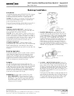
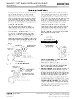
Page 27: ... than one minute the backstop is classified as an indexing device and must be referred to the Factory Installation Backstop Added to Existing Drive Only 1 DRIVE PREPARATION Drain oil from drive Remove fasteners Ref 27 end cover Ref 23 and gasket Ref 16 Figure 1 Keep Size 5115J and 5207J end covers Size 5207J fasteners and all lock washers for reuse all other parts may be discarded 2 BACKSTOP PREPA...

Page 28: ...ion Figure 4 Fill to oil level specified in Section I with oil specified in Appendix A Check motor for correct rotation before completing connection to drive BACKSTOP REPLACEMENT IN EXISTING DRIVES WITH DAMAGED BACKSTOPS 5 DISASSEMBLY EXTERNAL PARTS Drain oil from drive and remove backstop cover fasteners backstop end cover gasket s cover spacer where used and spider where used Save all metallic p...

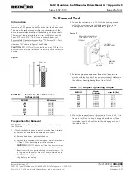
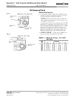
Page 29: ...ck in the sling before proceeding 2 Loosen the setscrew on the O D of the bushing nut and select the most convenient of the tapped holes in the housing face for the threaded adapter Figure 2 3 Select the proper adapter from the tool kit Adapters are marked with the Quadrive Size and part number Make sure the tapped hole in the housing face is clean before inserting the adapter Apply tightening tor...

Page 30: ...ive end 6 ALTERNATE METHOD Torque may be applied to the sheave or sprocket mounted on the input shaft Rexnord Industries LLC 3001 W Canal St Milwaukee WI 53208 4200 USA 378 200 PN 2128394 Telephone 414 342 3131 Fax 414 937 4359 November 2010 e mail info rexnord com web www rexnord com Supersedes 6 07 TABLE 3 Maximum Torque H S Shaft lb ft Nm DRIVE SIZE Drive Reduction J05 J09 J14 J25 5107 164 223 ...

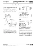
Page 31: ...lling a belt guard Refer to Appendix L for installation of Falk V Belt guards WARNING Remove all external loads from system before servicing drive or accessories 1 ASSEMBLE MOTOR MOUNT Loosely assemble support legs to the base plate support as shown in Figure 1 NOTE Nuts on inside for Sizes 5107 thru 5115 Nuts on outside for Sizes 5203 thru 5315 For NEMA motor frames 254 and larger or IEC motor fr...

Page 32: ...terial which may cause slippage Inspect the V belt drive periodically re tighten belts if they are slipping Rexnord Industries LLC 3001 W Canal St Milwaukee WI 53208 4200 USA 378 200 PN 2128394 Telephone 414 342 3131 Fax 414 937 4359 November 2010 e mail info rexnord com web www rexnord com Supersedes 6 07 S SHORT CENTERS M M EDIUM CENTERS L LONG CENTERS TABLE 2 Support Leg Fastener Quantity Each ...

Page 33: ...l level High Speed Shaft Up Figure 2 1 After installing the drive per the Owners Manual installation instructions determine which of the upper four side plug locations on the drive will provide the best location for the standpipe observing clearance required to remove dipstick Dimension D Table 1 Discard the air vent When the air vent location is not used for the standpipe relocate the pipe plug f...

Page 34: ...7 5 12 STD 5107 13 20 375 E P 5115 375 E P 5203 5207 KIT 0786775 5215 thru 5315 KIT 0786776 5107 375 E P 5115 375 E P 5203 5207 KIT 0786775 5215 thru 5315 KIT 0786776 5107 KIT 0738540 5115 STD 5203 375 E C 375 X 1 00N 5207 375 E C 375 X 2 00N 5215 500 E C 500 X 2 00N 5307 500 E C 500 X 2 50N 5315 500 E C 500 X 2 50N 5107 5115 STD 5203 375 E C 375 X 1 00N 5207 375 E C 375 X 1 50N 5215 500 E C 500 X...

Page 35: ...500 X 4 00N KIT 0738471 5107 5 15 375 E P 5107 16 30 375 E C 375 X 1 00N KIT 0786775 5115 5 15 375 E P 5115 16 30 375 E C 375 X 2 00N KIT 0786775 5203 5 30 375 E C 375 X 1 50N 5207 5 30 375 E C 375 X 2 00N 5215 5 30 500 E C 500 X 2 50N 5307 5315 5 30 500 E C 500 X 2 50N Q This oil level applies when only a street elbow with a pipe plug is used 6 O Clock H S S Up 9 O Clock H S S Up 12 O Clock H S S...

Page 36: ...66 5115 9 357 27 50 19 96 5203 9 179 21 38 14 71 5207 9 492 23 43 13 66 5215 8 997 29 53 13 64 5307 9 131 25 47 14 68 5315 9 131 25 47 14 68 Type J14 Tooth Combinations DRIVE SIZE Exact Ratio Input Output Pinion Ref 1A3 Gear Ref 1A4 Pinion Ref 2A3 Gear Ref 4A4 5107 14 43 19 54 13 66 5115 13 95 21 58 19 96 5203 14 45 20 57 14 71 5207 14 47 20 57 13 66 5215 13 60 21 58 13 64 5307 14 03 18 52 14 68 5...

Page 37: ... 197 99 3 75 95 3 2 00 50 8 1 19 30 2 875 9 2 50 63 5 750 500 3 50 5307 875 22 23 5 875 149 22 3 878 98 501 4 100 104 14 875 22 22 3 413 86 69 8 320 211 33 4 46 113 3 2 04 51 8 1 27 32 2 1 000 8 2 75 69 8 875 625 5 00 5315 1 000 25 40 6 000 152 40 4 433 112 598 4 664 118 47 1 000 25 40 3 871 98 32 8 710 221 23 4 75 120 7 2 00 50 8 1 27 32 2 1 000 8 2 75 69 8 1 000 750 5 00 H Dimensions are for ref...

Page 38: ...ommendations shown and the bushing selected for the proper shaft diameter remove and discard the retaining ring and spanner nut from the bushing assembly Slide the bushing flange end first onto the drive shaft until it contacts the shoulder on the shaft Insert the key through the bushing and into the drive shaft keyway Install the retaining ring into the groove in the drive shaft Bring the drive i...

Page 39: ...C dimensions is the variation which may occur due to axial compression and manufacturing tolerances Negative C dimensions indicate that the bushing protrudes beyond the mounting surface l The D dimension is the recommended minimum bore which clears the TA Taper bushing flange n Shaft diameter tolerances are per AGMA as follows to 1 50 000 004 over 1 50 to including 2 50 000 005 over 2 50 to includ...

Page 40: ... be fixed in position after the seal housing is assembled over the drive shaft see Figure 2 ALL JSC DRIVES Slide the bushing large end first onto the drive shaft until it contacts the shoulder on the shaft Insert the key through the bushing and into the drive shaft keyway Install the retaining ring into the groove in the drive shaft Line up the keyway in the drive hollow shaft with the key in the ...

Page 41: ...78 56 8 500 215 90 3 560 90 42 3 266 82 96 3 4375 3 500 88 90 3 263 3 251 0 103 0 108 Spir O Lox RSN 343 0 875 0 4375 8 250 209 55 1 000 8 2 50 63 5 0 375 s 9 52 4 250 107 95 Kit consists of Bushing thrust plate fastener key retaining ring and hardware The range of C dimension is the variation which may occur due to axial compression and manufacturing tolerances l Shaft diameter tolerances are per...

Page 42: ...elt Guard Installation for Drives without Shaft Fan 1 ASSEMBLE MOTOR MOUNT AND MOTOR TO DRIVE AS INSTRUCTED IN APPENDIX D 4 ASSEMBLE THREADED RODS TO BACKPLATE MOUNT SLOT COVER S AS REQUIRED ALLOW FOR BELT INSTALLATION ALLOW FOR BELT TAKE UP 2 ASSEMBLE BELT GUARD BRACKETS TO MOTOR MOUNT 5 MOUNT BELT DRIVE AS INSTRUCTED IN APPENDIX D MEDIUM CENTER POSITION SHORT LONG CENTER POSITION GUARD MOUNTING ...

Page 43: ...A V Belt Guard Installation for Drives with Shaft Fan 1 ASSEMBLE MOTOR MOUNT AND MOTOR TO DRIVE AS INSTRUCTED IN APPENDIX D 4 ASSEMBLE THREADED RODS TO BACKPLATE MOUNT SLOT COVER S AS REQUIRED 2 ASSEMBLE GUARD MOUNTING BRACKET ADAPTER 5 MOUNT BELT DRIVE AS INSTRUCTED IN APPENDIX D 3 ASSEMBLE BACKPLATE TO BRACKET FAN 6 MOUNT COVER AND APPLY WARNING LABEL ALLOW FOR BELT INSTALLATION ALLOW FOR BELT T...

Page 44: ...ortion of the cap screws and secure it to the shroud with four locknuts see Figure 2 6 Remove the condensation plug from bottom of the fan 7 Finish installing V belt guard assembly per installation instruction in Appendix L 8 Connect electric fan to power source per local and national electrical codes Rexnord Industries LLC 378 200 PN 2128394 3001 W Canal St Milwaukee WI 53208 4200 USA Telephone 4...

Reviews: