Falk
™
Drive One
®
Enclosed Gear Drives
•
Appendix A
Type D Series
•
Sizes M1130 thru M1210
(Page 13 of 27)
Rexnord Industries, LLC, 3001 W. Canal St., Milwaukee, WI 53208-4200
168-050
Telephone: 414-342-3131 Fax: 414-937-4359
January 2019
e-mail: info@rexnord.com web: www.rexnord.com
Supersedes 04-11
(PN 2124650)
Adjustable Torque Arm Installation
Introduction
The Drive One adjustable tie rod style torque arm is
available for all shaft-mounted Drive One sizes, parallel
shaft Type DH only. It is used to support the drive when
mounted in a standard horizontal position. Refer to the
Factory for other positions. The torque arm is mounted
directly to the drive with an anchor bracket. The torque
arm requires mounting holes in the driven equipment
support structure to provide for clevis bracket attachment.
The customer is responsible for determining the structural
integrity of their support member.
Mounting
It is natural for the drive system to move during operation.
This movement is due to run out from the driven equipment
shaft and gear drive low-speed shaft. Clearance in the
torque arm assembly will accommodate the motion of the
drive. To allow for the movement, the torque arm should
be centered at its attachment point on the drive system
and also centered in the clevis bracket on the support
member. Over-tightening or failure to center the torque
arm in the mounting will restrict the drive’s motion and will
result in premature failure of the drive or driven equipment.
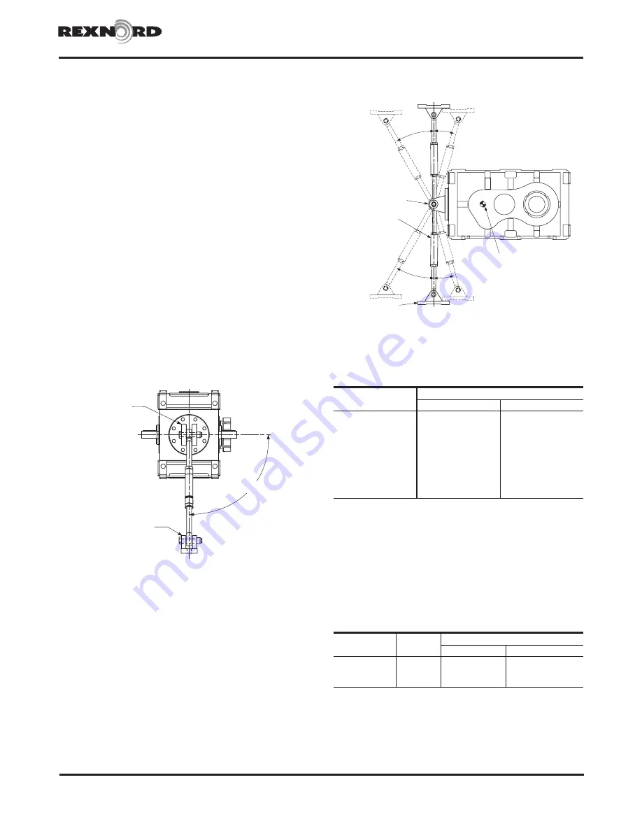
The torque arm should be perpendicular to the support
structure ± 2° when looking at the end of the drive. See
Figure 1.
ANCHOR
BRACKET
CLEVIS
BRACKET
90°
±
2°
Figure 1
Installation
1. Position the drive on the driven equipment shaft such
that the torque arm is perpendicular and centered in
the clevis mounted to the supporting structure and at its
attachment point on the drive system. Ideally, the clevis
bracket should be added to the structure after the drive
has been secured to the driven equipment.
NOTE: Do not fasten the torque to the support structure
at this time.
2. Secure the drive to the driven equipment via the TA
bushing or rigid coupling connection.
3. Check that the torque arm remains perpendicular and
centered in the clevis if mounted. If the torque arm is
not perpendicular and centered, reposition the drive on
the driven equipment shaft. If the clevis bracket is not
mounted, position and mount at this time.
4. The exact position of the torque arm may vary within
the range shown in Figure 2. For torque arm mountings
other than shown, refer to the Factory. If it is necessary
to shorten the torque arm assembly, cut the excess from
either tie rod end on Sizes M1130 through M1190 only.
30° MAX
3°
HIGH-SPEED SHAFT
ANCHOR
BRACKET
TORQUE ARM
ASSEMBLY
CLEVIS BRACKET
30° MAX
3°
Figure 2
Table 1 — Load Reaction Through Tie Rod
Drive
Size
Load
‡
N
lb
M1130
42700
9600
M1140
54500
12300
M1150
69500
15600
M1160
92300
20800
M1170
126000
25300
M1180
130000
29200
M1190
160200
36000
M1200
170300
38300
M1210
202900
45600
‡ Load includes moment due to motor and motor mount with torque arm at
maximum angle.
5. The support to which the clevis bracket is mounted
must sustain the load from the torque reaction shown in
Table 1. The maximum load reaction through the torque
arm occurs when the torque arm is located in the
extreme off angle position. Use Class 8.8 fasteners to
anchor the clevis bracket. Refer to Table 2 for fastener
size and tightening torque.
Table 2 — Tie Rod Clevis Bracket Fastener
Tightening Torque
Drive
Size
Fastener
Size
†
Tightening Torque - Nm (lb-ft)
Steel Foundation Concrete Foundation
M1130-M1140
M20 x 2.5
415 (305)
330 (246)
M1150-M1160
M24 x 3.0
705 (530)
570 (420)
M1170-M1210
M30 X 3.5
1440 (1060)
1150 (850)
† Class 8.8 fasteners required.
6. Bolt the torque arm to both the clevis bracket and the
drive anchor bracket and tighten the bolts until seated
against the brackets. DO NOT bend the bracket as
clearance between the clevis brackets and tie rod is
necessary.


