Falk
™
Drive One
®
Enclosed Gear Drives
•
Appendix D
Type D Series
•
Sizes M1130 thru M1210
(Page 17 of 27)
Rexnord Industries, LLC, 3001 W. Canal St., Milwaukee, WI 53208-4200
168-050
Telephone: 414-342-3131 Fax: 414-937-4359
January 2019
e-mail: info@rexnord.com web: www.rexnord.com
Supersedes 04-11
(PN 2124650)
Alignment-Free Assembly and Installation – Welded Design
Introduction
The Alignment-Free drive design consists of a shaft-
mounted drive, bell housing, motor adapter plate, torque
arm, motor and coupling. When assembled, the bell
housing, motor adapter, and motor locate off registers,
resulting in alignment of the motor and gear drive shafts.
Therefore, no additional alignment is required for the high-
speed coupling.
Assembly Instructions
The bell housing is fastened to the drive’s high-speed end
using cap screws through the four mounting holes on that
face (see Table 1 for size and torque). The bell housing will
locate on the bevel head of the drive. Read instructions
provided with high-speed coupling prior to assembly.
Table 1 — Tightening Torques
Drive
Size
Bolt
Size
Tightening Torque
N-m
lb-ft
M1150
M24
725
535
M1160
M24
725
535
M1170
M30
1450
1070
M1180
M30
1450
1070
M1190
M36
2530
1866
M1200
M36
2530
1866
M1210
M36
2530
1866
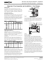
MOUNTING
POST
LONG
CAP SCREW
DRIVE
FAN
SEGMENT
FAN
ADAPTER
RING
Figure 1
Table 2 — Fan Mounting Tightening Torques
Fastener
Location
Fastener
Size
Tightening Torque
Nm
ft-lb
1420HFDD
M12
80
59
1480HFDD
M12
80
59
1584HFDD
M14
130
96
Fan Segment
M8
20
15
Fan Hub
‡
M6
10
7.5
‡ For close coupling only.
Table 3 — Coupling Gap
Fluid Coupling
Size
Tschan Hub
Size
Gap
mm
Inch
370HFDD
200
6.5
0.256
1420HFDD
230
7.5
0.295
1480HFDD
260
7.5
0.295
1584HFDD
300
8.4
0.331
1660HFDD
360
9.0
0.354
MOTOR
MOTOR
MOUNTING
FACE
MOTOR
ADAPTER
PLATE
BELL
HOUSING
DRIVE
SHAFT
SPACER
PROTRUSION
B
A
C
COUPLING
HUBS
Figure 2
Fluid Coupling
Location of the fluid coupling on the high-speed shaft of
the drive is determined by the provided shaft spacer. Install
the fluid coupling on the high-speed shaft of the gear drive
per fluid coupling instructions. If a shaft fan is required,
remove every other of the twelve delay fill chamber
fasteners. Install the fan adapter ring to the fluid coupling
using the long socket head cap screws provided. Place a
mounting post between the delay fill chamber flange and
the adapter ring as shown in Figure 1. After all fasteners
and mounting posts are installed, tighten cap screws to
the torque specified in Table 2. Install the six fan segments
to the outer bolt circle of the adapter ring. See Table 2 for
tightening torque.
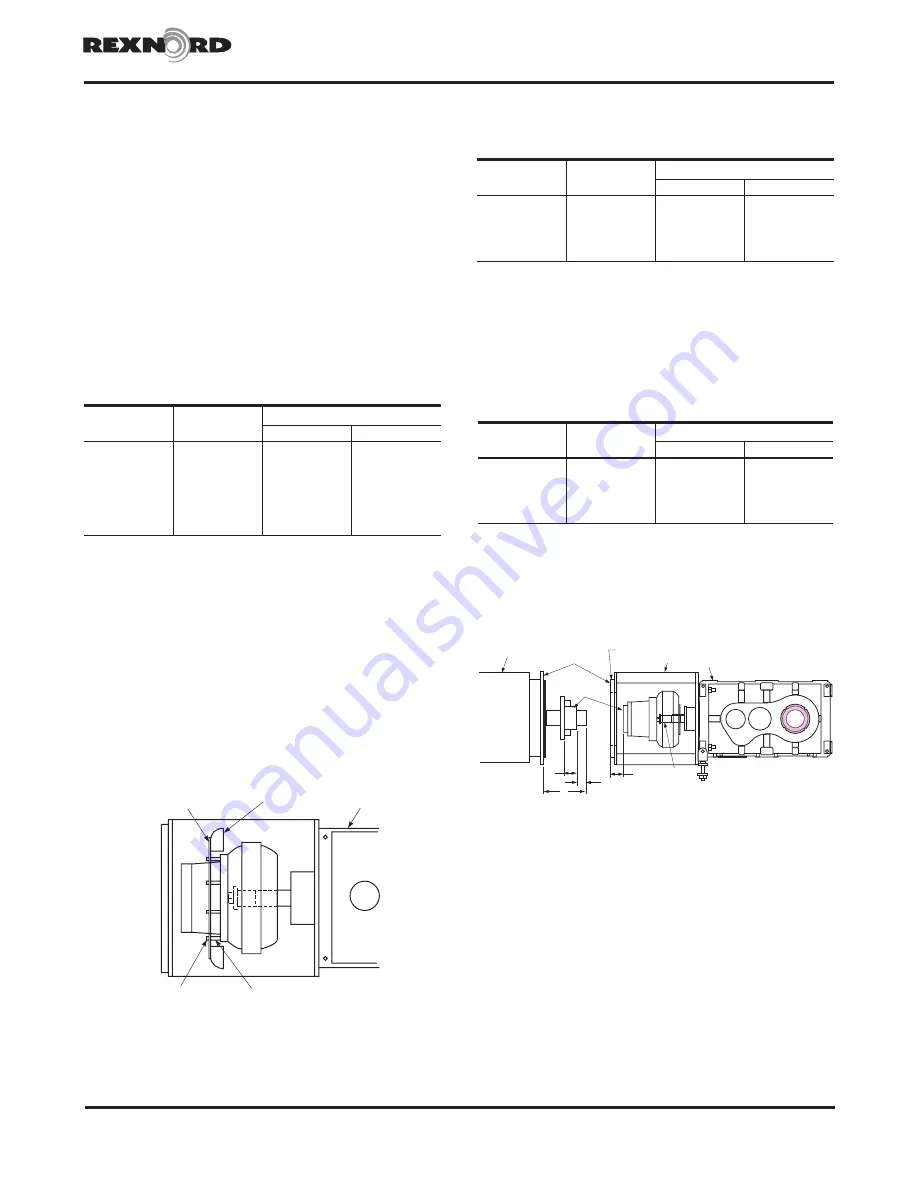
Once the fluid coupling is installed, the motor adapter plate
can be mounted to the bell housing, also being located
by a register. Measurements must be taken to accurately
position the motor half of the coupling hub on the motor
shaft. First, measure the distance from the motor mounting
face to the end of the motor shaft (A). Then measure the
distance from the motor adapter plate face to the hub on
the fluid coupling (B). Finally measure the distance from
the hub flange to the hub end (C). The desired gap can
be found in Table 3, based on coupling size.
Calculate the hub protrusion:
Protrusion = (A + Gap) – (B + C)
If the calculated protrusion is a negative value, the hub
overhangs the shaft by that amount (Figure 2).
Once the hub is correctly located on the motor shaft, the
motor can be mounted to the motor adapter plate. The
hubs will be aligned and come together to the proper gap.
To fill the fluid coupling to the proper oil level, align the
mark on the perimeter of the fluid coupling with the mark
in the center of the inspection window on the bell housing
on the side opposite the TA bushing nut or shaft extension.
To locate the correct mark on the fluid coupling, begin by
aligning the fill hole of the fluid coupling with the mark in
the inspection window. For fill angles less than 90°, rotate
the fill plug upward until the marks line up. For fill angles
greater than 90°, rotate the fill plug downward until the
marks line up. When the proper marks are in line, fill the
fluid coupling with recommended fluid until fluid appears
at the lip of the fill hole.


