Owners Manual • Rexnord
®
Planetgear
™
7000 Speed Reducers
(Page 3 of 33)
Size Mercury/Mars
158-110
10/21 (Supersedes 01/15)
© Rexnord Corporation. All Rights Reserved.
WELDING
— Do not weld on the gear drive or accessories
without prior approval from the Factory. Welding on the
drive may cause distortion of the housing or damage to the
bearings and gear teeth. Welding without prior approval
could void the warranty.
EFFECTS OF SOLAR ENERGY
— Special measures
should be taken to protect drives operating in direct
sunlight at ambient temperatures over 100°F (38°C).
This protection can consist of a canopy over the drive or
reflective paint on the drive. If neither is possible, a heat
exchanger or other cooling device may be required to
prevent the reducer sump temperature from exceeding the
allowable maximum oil temperature of 200°F (93°C).
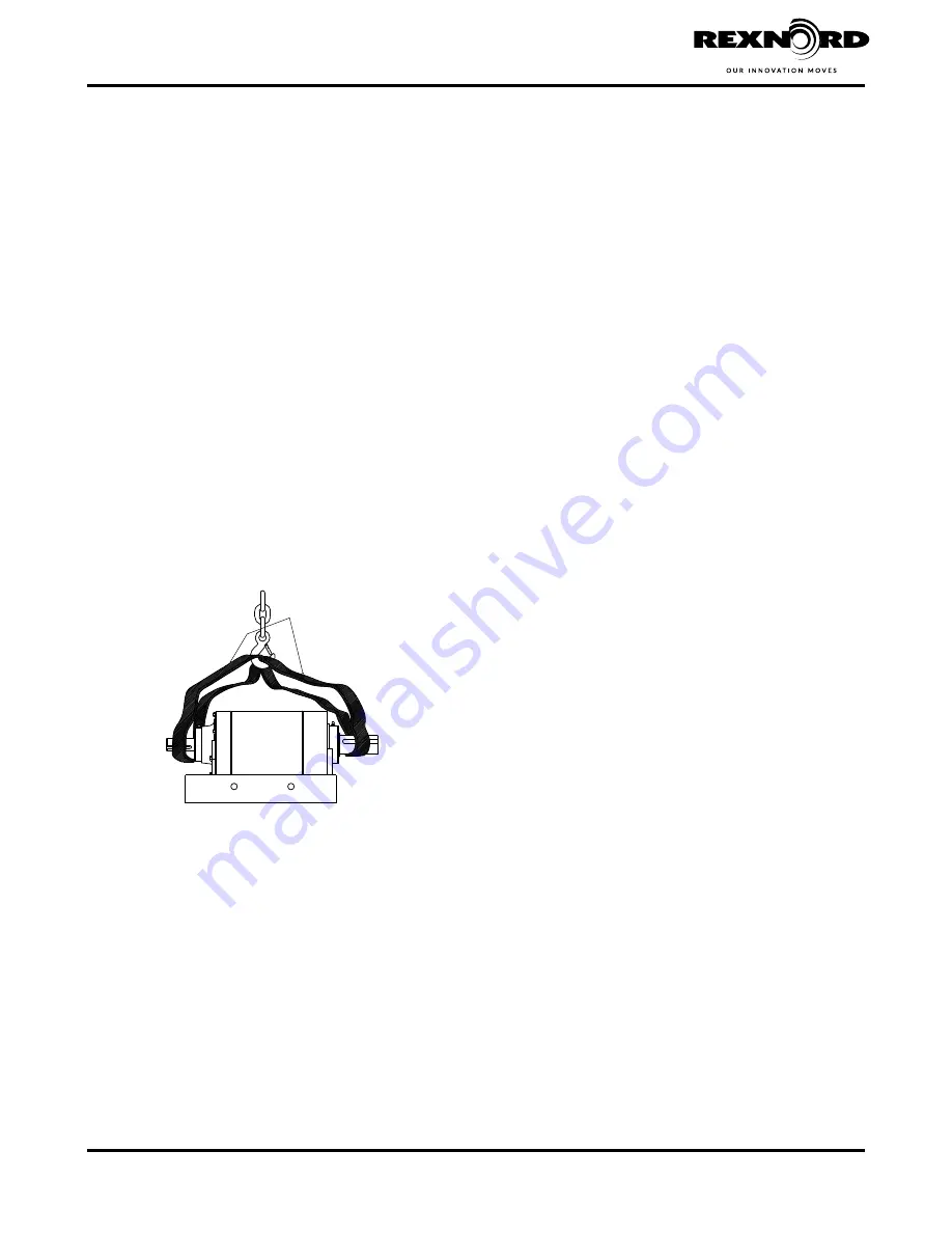
2.1 HANDLING OF SPEED REDUCER
Disconnect all mounting bolts from the reducer before
lifting. Use a double rope sling of ample strength, wrapped
around the input and the output shafts when lifting the
speed reducer; reference
Figure 2.1
. Reference
Table
(Page 29) for reducer weights. Be sure the reducer is
properly secured and balanced to prevent shifting during
suspension.
WARNING
: To avoid personal injury or product damage,
never attempt to lift the reducer with an eyebolt threaded
into the top of the reducer maincase.
2.2 REDUCER MOUNTING
It is essential that the speed reducer be securely bolted to
a solid, level, and vibration free foundation.
If the reducer mounting surface is not horizontal, refer
(Page 29) for Maximum Allowable Tilts for
Standard Reducers.
NOTE: If the reducer is tilted,the oil requirements may
change.
Bolts should be of the correct size to fit mounting holes.
They should be SAE Grade 5 or equivalent (Grade 8.8
or better for metric applications). Fasteners shall be
torqued according to
Table 18
(Page 29). The use of a
rigid structural steel base-plate is strongly recommended
as a foundation. If a concrete foundation is used, grout
structural steel mounting pads into the concrete rather
than grouting the reducer directly into the concrete. Allow
the concrete to cure before torquing the reducer mounting
bolts down.
Align the reducer with driven equipment by placing broad
flat shims underneath all mounting pads of the reducer.
Start at the low speed end and level across the length
and width of the reducer. Check with a feeler gauge to
make certain there is no clearance and that all pads are
supported to prevent distortion of housing when reducer is
bolted down. After the reducer has been aligned with the
driven equipment and bolted down, align prime mover to
the reducer input shaft. If the reducer is received coupled
to a motor, it has been aligned properly at the factory.
However, because alignment may have been disturbed
during shipment, it is best to check alignment and then
realign if necessary. The reliability and long life of the
reducer requires careful installation of accessories and
accurate alignment of the connecting shafts. Check final
alignment of motor shaft, coupling, and reducer shaft after
reducer is in final working position.
Section II — Installation
DOUBLE ROPE
SLING
Figure 2.1 Reducer Handling


