10
Smart Condition Monitoring System Electrical and Communications Manual
Transducer Connection
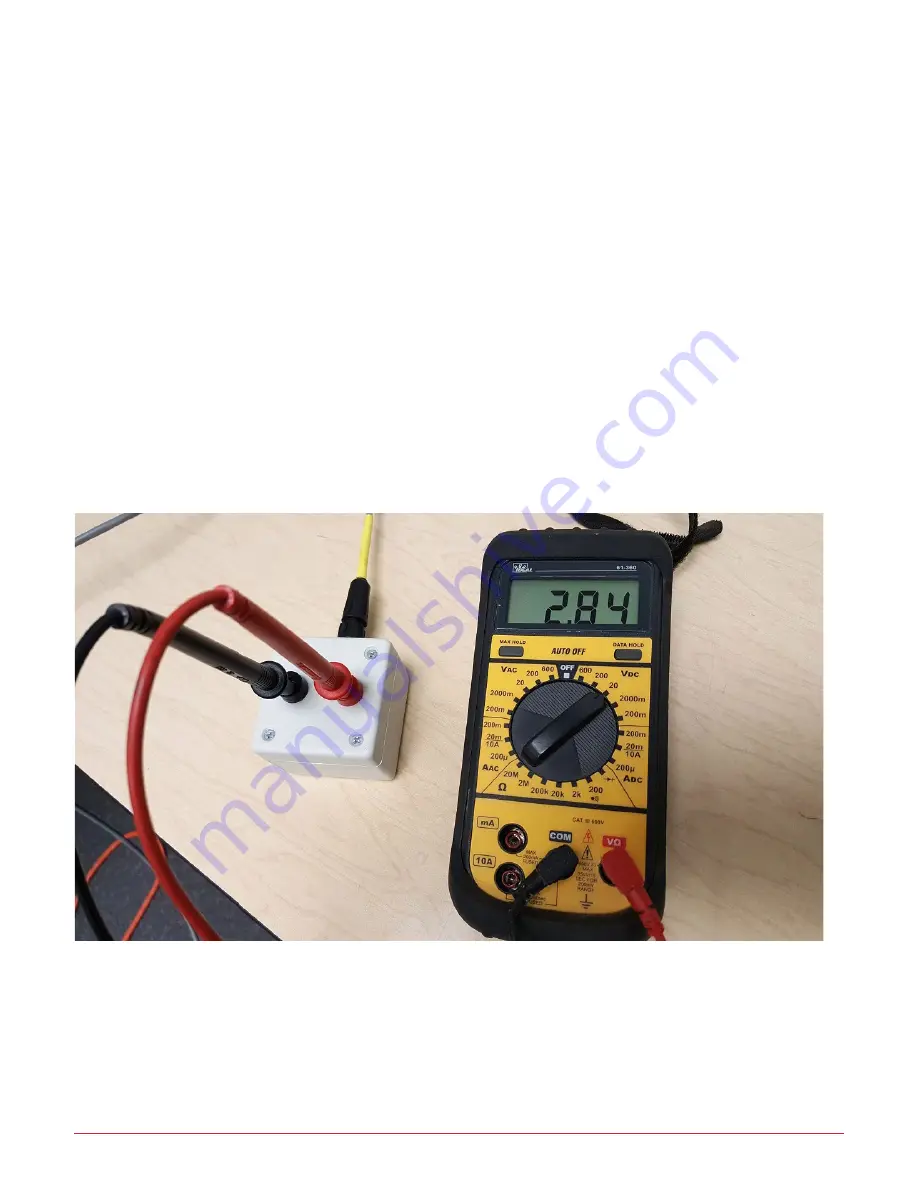
8. If the meter displays a positive value less than 5V dc, this test is complete, tighten the cable gland, disconnect the
cable from the test box and connected to the converter box. If the multimeter displays a negative DC voltage
reading the wires inside the cable joint are reversed. Unscrew the gland nut and the screw terminal cover,
disconnect the wires and swap them over, then tighten them securely.
Caution: the equipment must be turned off or the test signal deactivated before the cable joint is opened or damage to the
customer PLC or CT could occur. Tighten down the screw terminal cover and the cable gland nut, reconnect to the PLC
or customer CT at the head end and repeat 7) above ensuring the multimeter displays a positive voltage reading
then disconnect the cable from the test box and connect it to the small black converter box.
9. If the multimeter reads more than +5V dc or less than -5V dc, further investigation by a qualified electrical
technician is required. If the signal is to the correct 4-20mA signal, a multimeter connected red to red and black to
black on the test box will never show greater than +5V dc or less than -5V dc. If the voltage is out of range, do not
connect the CT cable to the converter box.
10. If, and only if, a successful test was achieved, remove the polarity test box and connect the EN2 connector on the end
of the cable from the LCVC8001 to the lower Left Hand (Yellow) port on the converter box. Check that after the
equipment is back in service that motor power draw is being sent to the cloud and the scaling factor has been
correctly set.
11. Pack Polarity check box in toolkit and move to next job.
Step E


