7
Smart Condition Monitoring System Electrical and Communications Manual
ATTACHING THE SUPPLIED ETHERNET CONNECTOR TO CAT 5 CABLE
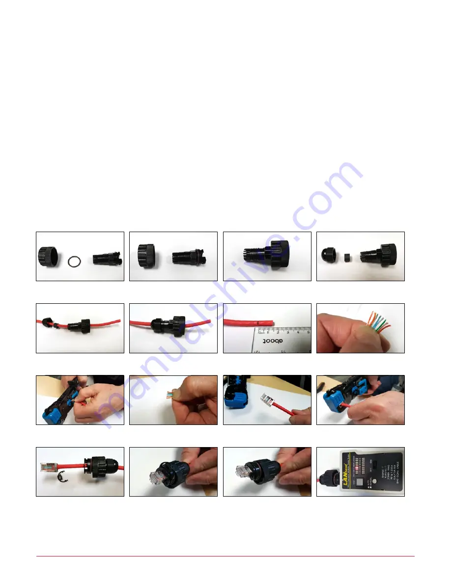
1. Place sealing “O” ring over connector body and slide coupling ring onto body (
Steps A, B then C
).
2. Slide sealing nut, cable grip grommet and assembly just created onto cable. Push the grommet into the connector
body then loosely tighten the sealing nut (
Steps D, E then F
).
3. Strip the outer sheath of the cable back 14mm, untwist and straighten the 8 core wires and arrange the colors as
required for EIA/TIA 568B (Orange/White, Orange, Green/White, Blue, Blue/White, Green, Brown/White,
Brown - pins 1 to 8) then trim to a neat straight line (
Steps G, H then I to give J
).
4. Push the wires into the clear RJ45 connector. Pin 1 is to the left when the cable is facing you and the tang is
under the connector as shown in
Step K
.
5. Crimp the wire cores into the RJ45 connector using suitable crimping pliers (
Step L
).
6. Gently pull the RJ45 plug back into the connector shell, slip the snap ring onto the connector body and push
firmly until it snaps into place locking the plug into the connector body (
Steps M, N then O
).
7. Test the completed cable end to end with a suitable LAN cable tester.
Step A
Step B
Step C
Step D
Step E
Step F
Step G
Step H
Step I
Step J
Step K
Step L
Step M
Step N
Step O
Step P
Data Cable Connection


