8
Smart Condition Monitoring System Electrical and Communications Manual
Transducer Connection
CONNECTING THE REXNORD SUPPLIED
CURRENT TRANSDUCER
Electrical Connections
(tool needed 1/8" or 3mm blade screwdriver)
Input Connections
Current Measurements
The transducers sense current in a non-contact fashion by
simply running the wire carrying the current through the
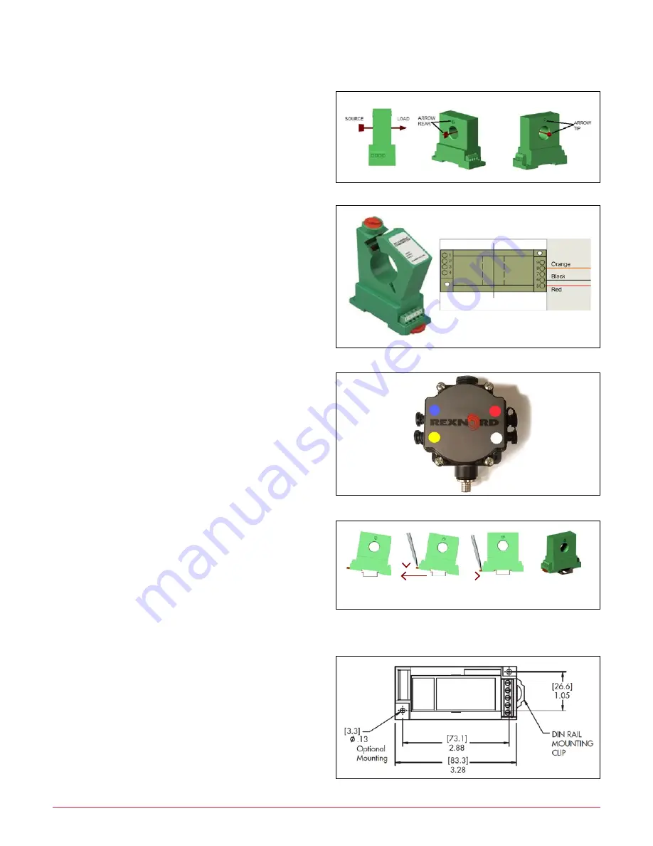
hole of the transducer. If installing the DC version, pay close
attention to the direction as shown below
(Figure 13)
.
All non-contact current measurements are based upon a
single phase wire going through the hole. Wire the CT cable
to the CT as shown in
Figure 14
.
Connecting to the Rexnord Edge
Converter Box
If the molded connector end of the CT cable is not already
connected, please attach to terminal 4 (Yellow) on the small
black converter box mounted next to the Edge
(Figure 15)
.
Mounting and Mechanical
Din Rail Mounting (tool needed 3mm blade screwdriver)
1. Hook the stationary lip of the bottom case to one side of
the 35mm DIN Rail. (The side without the orange clip.)
2. Using the blade screwdriver, push down and pull out on
the orange rail clip of the bottom case till the transducer
clicks over the other side of the rail.
3. Once it is latched on fully, push the clip in towards the
transducer to fully seat the transducer on the rail
(
Figure 16
).
Figure 13
Figure 16
1
2
3
Figure 14
Figure 15
Screw Mounting (Screws are not supplied)
DO NOT over tighten the mounting screws.


