30/76 Mounting
Bosch Rexroth AG
, CytroPac, RE 51055-B/02.2021
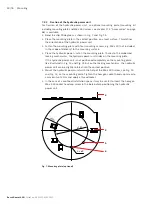
7.2.2 Fixation of the hydraulic power unit
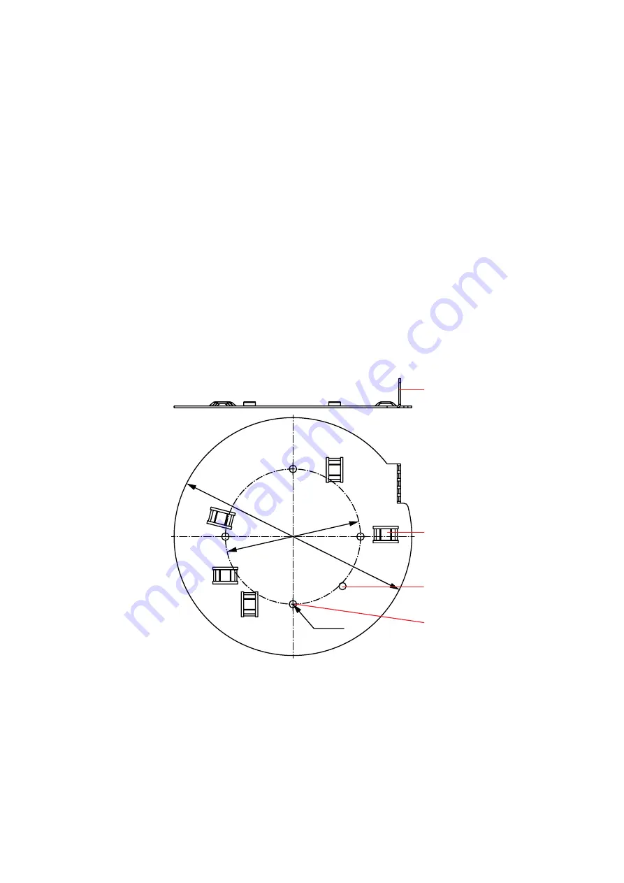
For fixation of the hydraulic power unit, an optional mounting plate (mounting kit
including mounting plate and M6 x 430 screw, see chapter 17.4 “Accessories“ on page
68) is available.
▶
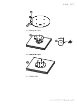
Bend the clip 90 degrees as shown in Fig. 7 and Fig. 15.
▶
Place the mounting plate in the correct position on a level surface. This defines
the orientation of the hydraulic power unit.
▶
Fasten the mounting plate with four mounting screws, e.g. M8 x 20 (not included
in the scope of delivery) to the mounting surface.
▶
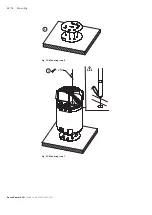
Place the hydraulic power unit on the mounting plate. Thanks to the embossed
locking mechanisms, the hydraulic power unit slides on the mounting plate.
If the hydraulic power unit is not positioned completely on the mounting plate
like illustrated in Fig. 14 und Fig. 15 but on the locking mechanisms, the hydraulic
power unit can be slightly rotated into the correct position.
▶
Mount the hydraulic power unit with the help of the M6 x 430 screw, see Fig. 13
and Fig. 14, on the mounting plate. Tighten the hexagon socket head cap screw to
a maximum of 2 Nm and apply a thread locker.
▶
In the case of a confined installation space it may be useful to insert the hexagon
M6 x 430 socket head cap screw in the bore before positioning the hydraulic
power unit.
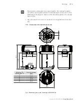
Fig. 7: Mounting plate (optional)
ø285
ø162
4 x ø9
4
5
6
3

