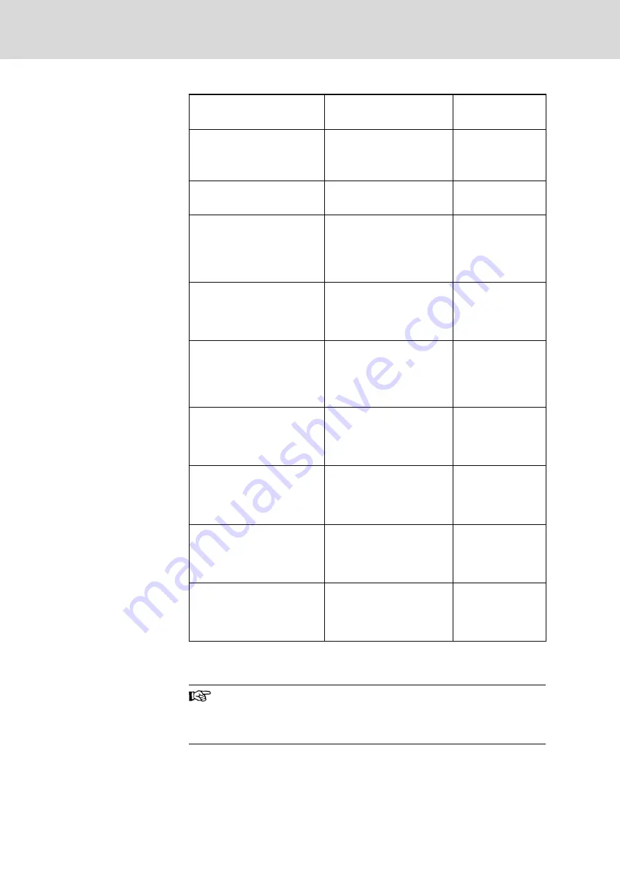
Device to the left
Device to the right
Dimension Z
[mm]
HCS02.1E-W0012
HCS02.1E-W0028
HLB01.1C
HCS02.1E-W0012
HCS02.1E-W0028
HLB01.1C
70
HCS02.1E-W0054
HCS02.1E-W0070
HCS02.1E-W0054
HCS02.1E-W0070
55
HLC01.1C-01M0
HLC01.1C-02M4
HCS02.1E-W0054
HCS02.1E-W0070
HLC01.1C-01M0
HLC01.1C-02M4
50
(without a distance
between the devi‐
ces)
HCS02.1E-W0012
HCS02.1E-W0028
HLB01.1C
HLC01.1C-01M0
HLC01.1C-02M4
57,5
(without a distance
between the devi‐
ces)
HCS02.1E-W0054
HCS02.1E-W0070
HLC01.1C-01M0
HLC01.1C-02M4
HCS02.1E-W0012
HCS02.1E-W0028
HLB01.1C
62,5
HCS03.1E-W0070
HCS03.1E-W0100
HCS03.1E-W0150
HCS03.1E-W0070
HCS03.1E-W0100
HCS03.1E-W0150
50
(without a distance
between the devi‐
ces)
HCS03.1E-W0210
HCS03.1E-W0210
100
(without a distance
between the devi‐
ces)
HCS03.1E-W0070
HCS03.1E-W0100
HCS03.1E-W0150
HCS03.1E-W0210
75
(without a distance
between the devi‐
ces)
HCS03.1E-W0210
HCS03.1E-W0070
HCS03.1E-W0100
HCS03.1E-W0150
75
(without a distance
between the devi‐
ces)
Tab.11-4:
Table for Dimension Z
Combination of Drive Controllers of the Rexroth IndraDrive C and M Product Ranges
The accessory HAS04 requires additional mounting clearance at
the HCS arranged at the utmost left position.
Rexroth IndraDrive M devices are arranged in line to the right
starting from the supplying drive controller HCS.
Bosch Rexroth AG
DOK-INDRV*-SYSTEM*****-PR06-EN-P
Rexroth IndraDrive Drive Systems with HMV01/02 HMS01/02, HMD01, HCS02/03
200/309
Arranging the Components in the Control Cabinet


