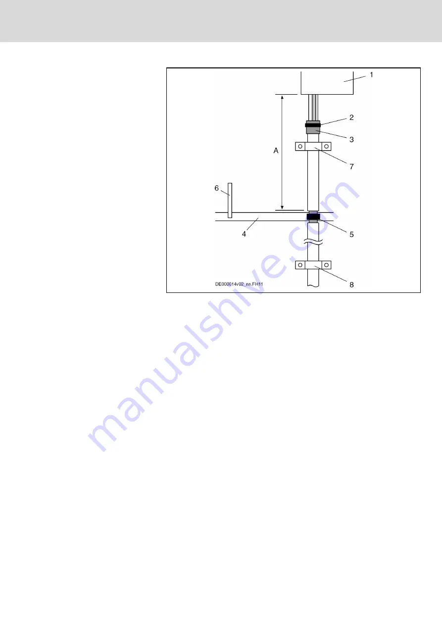
1
Drive controller
2
Cable tie
3
Overall shield of the motor power cable folded back
4
Ground bus in control cabinet
5
Connection between overall shield of motor power cable laying bare
and ground bus
6
Connection of ground bus to supplying device
7
Strain relief (as near as possible to the drive-side cable end)
8
Strain relief (as near as possible to exit point from control cabinet)
A
Cable length between ground bus and device: < 1 m
Fig.13-17:
Shield Connection, Alternative 2
●
With a cable tie (2), press drive-side cable end in such a way that
shields of two inner pairs of wires (motor temperature, holding brake)
have good contact with overall shield of motor power cable (3). (If you
use your own cable, make sure the shields of the two inner pairs of
wires are in contact with the overall shield.)
●
On level of ground bus in control cabinet, remove a piece of cable
sheath from motor power cable in order to lay bare the overall shield (5).
●
Connect overall shield (5) to ground bus in control cabinet with an ap‐
propriate connection (clip). The connection must have a cross section of
at least 10 mm
2
.
●
With a cable (6) (line cross section: at least 10 mm
2
), connect ground
bus (4) to ground connection at supplying device (Rexroth IndraDrive
supply unit or Rexroth IndraDrive drive controller HCS).
●
Make sure there is sufficient strain relief for motor power cable as near
as possible to drive-side cable end (7).
●
In addition, make sure there is sufficient strain relief for motor power ca‐
ble as near as possible to exit point from control cabinet of motor power
cable (8).
DOK-INDRV*-SYSTEM*****-PR06-EN-P
Rexroth IndraDrive Drive Systems with HMV01/02 HMS01/02, HMD01, HCS02/03
Bosch Rexroth AG
239/309
Connections of the Components in the Drive System


