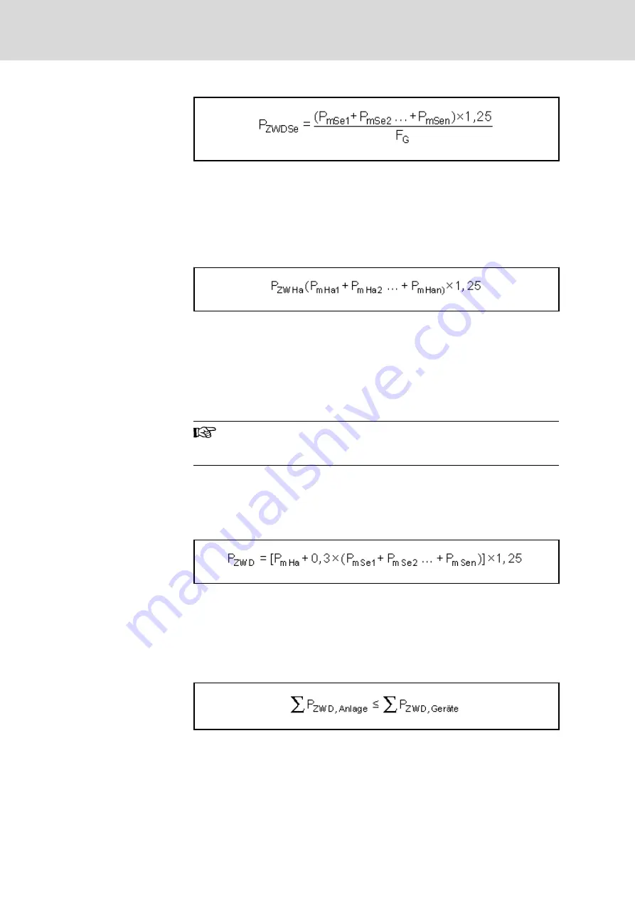
P
ZWDSe
DC bus continuous power for servo drives [kW]
P
mSe1
…
P
mSen
Mechanical continuous power for servo drives [kW]
F
G
Simultaneity factor
1,25
Constant for motor and controller efficiency
Fig.15-8:
DC Bus Continuous Power for Servo Drives
DC Bus Continuous Power for
Main Drives
If several main drives are operated at one DC bus, the simultaneously re‐
quired DC bus continuous powers must be added:
P
ZWHa
DC bus continuous power for main drives [kW]
P
mHa1
…
P
mHan
Mechanical continuous power for main drives [kW]
1,25
Constant for motor and controller efficiency
Fig.15-9:
DC Bus Continuous Power for Main Drives
Chokes and additional capacitors have to be selected in accordance with the
actually required DC bus continuous power. It is determined by the nominal
power of the main drives.
When selecting the drive controllers, make sure that their maxi‐
mum DC bus continuous power will not restrict the short-time op‐
eration power of the main drives.
DC Bus Continuous Power for
Main and Servo Drives
When main and servo drives are operated at a drive controller, the required
DC bus continuous powers must be added.
At a typical NC machine tool, the required DC bus continuous power will be
primarily defined by the main drive. Accordingly, the following equation is to
be used for such applications:
0,3
Empirical value for standard machine tools
1,25
Constant for motor and controller efficiency
P
ZWD
DC bus continuous power [kW]
P
mSe1
…
P
mSen
Mechanical continuous power for servo drives [kW]
P
mHa
Nominal power for main drive (shaft output) [kW]
Fig.15-10:
DC Bus Continuous Power for Main and Servo Drives at NC Machine
Tools
P
ZWD,Anlage
Generated DC bus continuous power of the installation
P
ZWD,Geräte
Allowed DC bus continuous power of the devices
Fig.15-11:
Supply Condition: DC Bus Continuous Power
Bosch Rexroth AG
DOK-INDRV*-SYSTEM*****-PR06-EN-P
Rexroth IndraDrive Drive Systems with HMV01/02 HMS01/02, HMD01, HCS02/03
250/309
Calculations


