11.1.3
Boring Dimensions for the Mounting Plate
Individually Arranged Devices
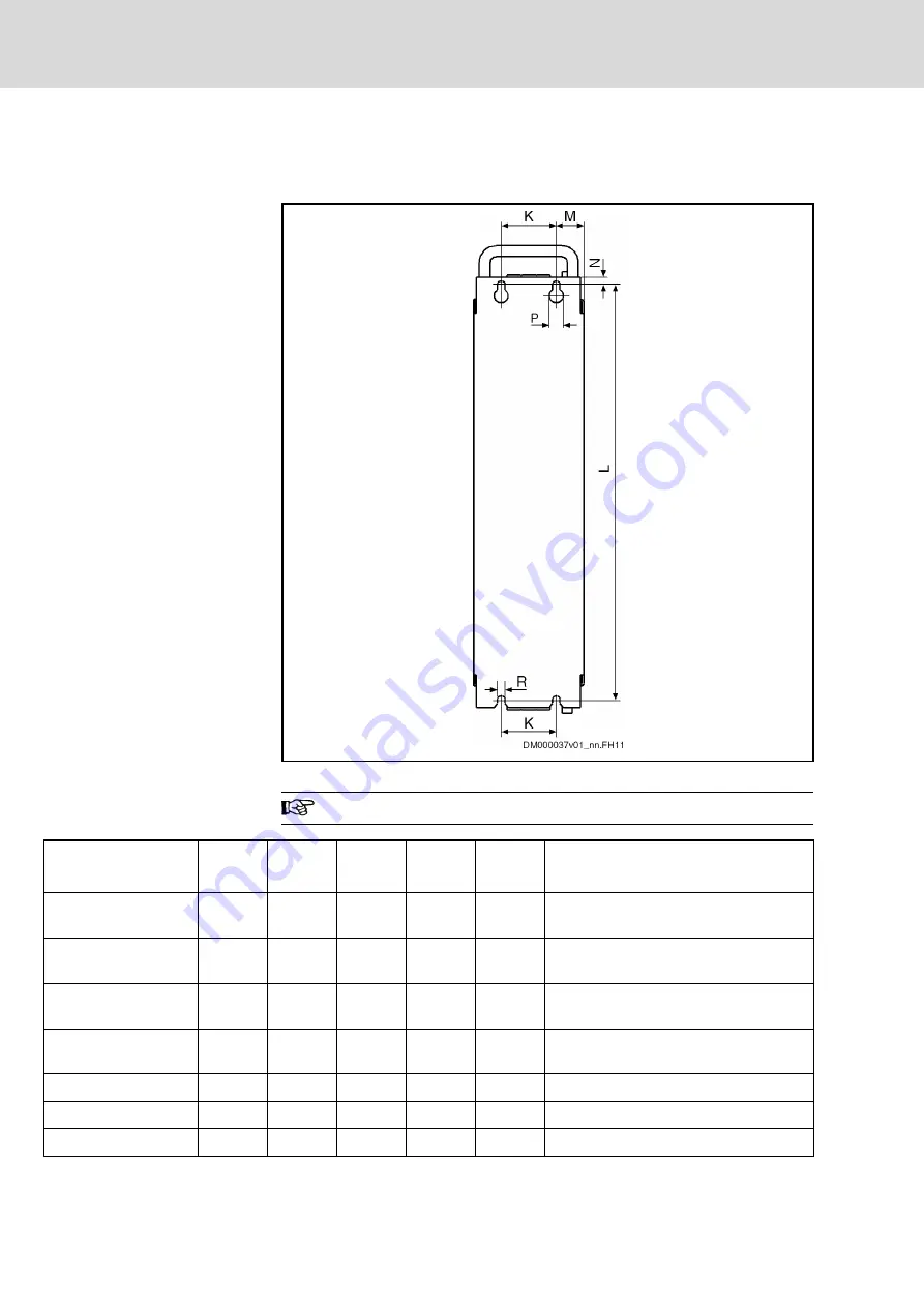
Fig.11-4:
Boring dimensions
The figure shows the back of a device.
Device
K
[mm]
L
[mm]
M
[mm]
P
[mm]
R
[mm]
Notes
HCS02.1E-W0012
0
316
32,5
13
7
Observe additional distance to lateral
neighboring devices
HCS02.1E-W0028
0
378
32,5
13
7
Observe additional distance to lateral
neighboring devices
HCS02.1E-W0054
55
378
25
13
7
Observe additional distance to lateral
neighboring devices
HCS02.1E-W0070
55
378
25
13
7
Observe additional distance to lateral
neighboring devices
HCS03.1E-W0070
75
466
25
13
7
HCS03.1E-W0100
175
466
25
13
7
HCS03.1E-W0150
175
466
25
13
7
Bosch Rexroth AG
DOK-INDRV*-SYSTEM*****-PR06-EN-P
Rexroth IndraDrive Drive Systems with HMV01/02 HMS01/02, HMD01, HCS02/03
194/309
Arranging the Components in the Control Cabinet


