of view. These points of view include aspects of performance-dependent ar‐
rangement and electromagnetically compatible installation.
11.2.2
Performance-Dependent Arrangement
Arrangement With HMV
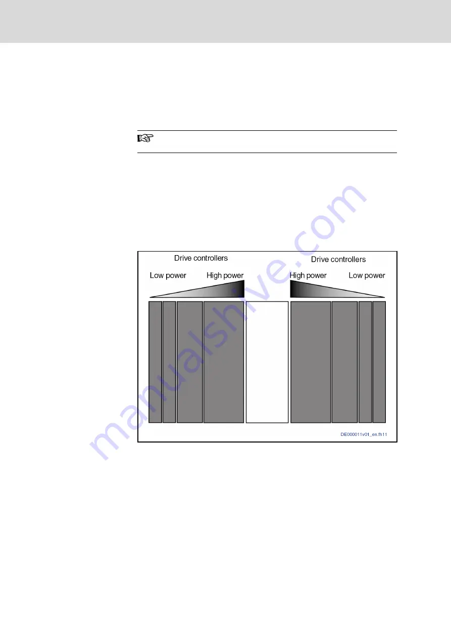
The HMV01 supply units can supply HMS and HMD drive controllers on both
sides.
When you use HNS02 and HNL02, the supply units HMV02 only
allow mounting them on one side to the right.
●
Arrange drive controllers according to their performance. Arrange drive
controllers with high performance as close to the supply unit as possi‐
ble. Ideally, the drive controllers should be distributed equally to the left
and right side of the supply unit.
●
Arrange DC bus capacitor unit (HLC) next to the supply unit.
●
Arrange DC bus resistor unit (HLB) next to the supply unit.
●
When simultaneously using DC bus resistor unit and DC bus capacitor
unit in a drive system, arrange the DC bus capacitor unit between sup‐
ply unit and DC bus resistor unit.
Fig.11-7:
Example of Arrangement
Arrangement With HCS
When you operate HCS converters in the type of mains connection "central
supply", place the supplied drive controllers to the right of the HCS convert‐
ers.
●
Arrange DC bus capacitor unit next to drive controller with the greatest
DC bus continuous power.
●
Arrange DC bus resistor unit next to drive controller with the greatest re‐
generative power.
●
When simultaneously using DC bus resistor unit and DC bus capacitor
unit in a drive system, arrange the DC bus capacitor unit to the right of
HCS and the DC bus resistor unit to the right of the DC bus capacitor
unit.
Bosch Rexroth AG
DOK-INDRV*-SYSTEM*****-PR06-EN-P
Rexroth IndraDrive Drive Systems with HMV01/02 HMS01/02, HMD01, HCS02/03
202/309
Arranging the Components in the Control Cabinet


