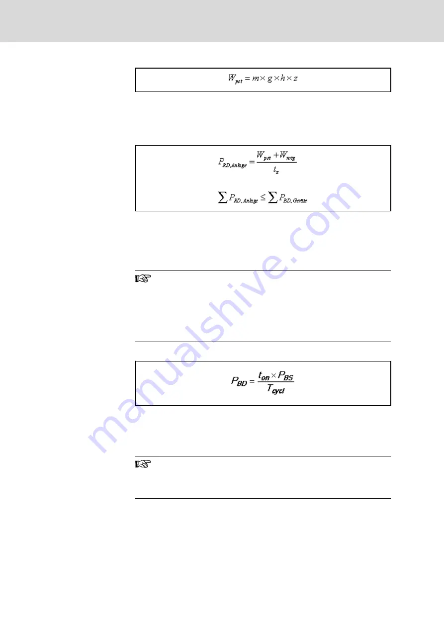
W
pot
Potential energy [Ws]
m
Load mass [kg]
g
Gravitational acceleration = 9.81 m/s²
h
Lowering height [m]
z
Number of lowering processes per cycle
Fig.15-22:
Potential Energy of Non-Balanced Masses
P
RD,Anlage
Generated continuous regenerative power [kW]
P
BD,Geräte
Allowed braking resistor continuous power [kW]
t
z
Cycle time [s]
W
potg
Sum of potential energies [kWs]
W
rotg
Sum of rotary energies [kWs]
Fig.15-23:
Continuous Regenerative Power
Influence of efficiency
The continuous regenerative power occurring in the steady-state
condition in the majority of cases is less than the calculated ener‐
gy absorption, because all involved components (such as load,
gear, motor, cables) absorb a part of the regenerative energy.
Only reduce the generated continuous regenerative power when
the efficiency behavior is known.
Continuous Power of Braking Re‐
sistor
Continuous power of the braking resistor:
P
BD
Allowed continuous power of braking resistor
t
on
Allowed duty cycle
P
BS
Allowed peak power of braking resistor
T
cycl
Allowed cycle time
Fig.15-24:
Braking Resistor Continuous Power
Several braking resistors (e.g. HLR) at common DC bus
With several braking resistors at the DC bus, the available contin‐
uous power is less than the sum of the individual continuous pow‐
ers.
Bosch Rexroth AG
DOK-INDRV*-SYSTEM*****-PR06-EN-P
Rexroth IndraDrive Drive Systems with HMV01/02 HMS01/02, HMD01, HCS02/03
256/309
Calculations


