Form I-XE/CRGB/RPB, Page 32
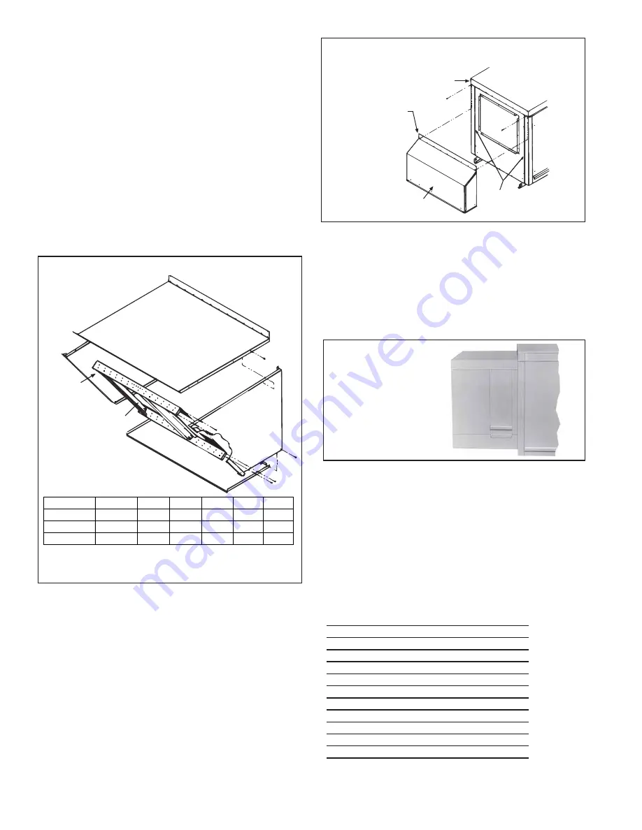
FIGURE 32 - Optional
Evaporative Cooling
Module is factory-
installed on the blower
cabinet
The optional evaporative cooling module is equipped with high effi-
ciency pad media of either 6" or 12" rigid cellulose (Option AS3 or AS4)
or 6" or 12" rigid glass fiber (Option AS5 or AS8). Six-inch media
provides 68% efficiency; 12" media provides 90% efficiency. Effi-
ciency values are stated at maximum allowable CFM without the addi-
tion of a moisture elimination pad with an inlet dry bulb temperature of
95°F and inlet wet bulb temperature of 65°F. The evaporative cooling
efficiency is a function of inlet temperature and of face velocity through
the media. The stated cooling efficiency will rise with the decrease of
CFM and the increase of inlet temperature. Moisture elimination pads
(Option ASA1) may be used on all units but are required on high CFM
units as listed below.
Heater
Moisture Elimination Pad Required
S i z e
on Evaporative Cooling Module
75
2601 - 2645 CFM
100
2601 - 3400 CFM
125
2601 - 3800 CFM
150
3201 - 4700 CFM
175
3201 - 5000 CFM
200
3701 - 5100 CFM
225
3701 - 5150 CFM
250
4501 - 5800 CFM
300
4501 - 6300 CFM
350
5101 - 6800 CFM
400
5601 - 7100 CFM
The standard water controls for the evaporative cooling module include
the float valve, the float switch, and pump assembly illustrated in the
following paragraphs. If the cooling module has an optional AquaSaver
TM
Top Panel (edge must be
underneath cabinet top)
Left Side
Panel
Right Side
Panel
Factory-assembled
Louver Assembly
including Moisture
Eliminating Louvers
(U.S. Patent 4,999,037)
and Screen
Bottom
Panel
NOTE:
Either a manufacturer designed optional air inlet hood as
shown in Paragraph 31 or an evaporative cooling module as shown
in Paragraph 33 is required to ensure complete weather resistance.
FIGURE 31 - Installation of Air Hood on Cabinets with
30% Outside Air Opening Options
Blower
Cabinet
Remove two corner and
compete row of screws
Slide top flange
underneath the
cabinet top
Vertical Slots -
Slide side flanges
into slots
30% Outside
Opening Air Hood
31. 100% Outside Air Hood (cont'd)
Hood Installation Instructions (cont'd)
FIGURE 30 - Assembly
Drawing of Option AS2
Outside Air Hood
3. Bottom Panel
- Position the air hood bottom panel so that it is to
the
inside
of the two side panels and
above
the factory-installed
support angle. Attach to the side panels.
If the bottom panel does not rest tightly against the support angle,
follow these instructions to adjust the position of the support angle:
a) Slightly loosen (do not remove the screws).
b) Slide the support angle up so that it is against the bottom
panel.
c) Tighten the screws.
Attach the support angle to the air hood bottom panel. The bottom
panel of the air hood and the support angle should be tight together;
do not draw with the sheetmetal screws.
4. Louver Assembly
- With the intake screen toward the inside of the
hood position the pre-assembled vertical louver assembly in the
inlet opening of the air hood. Using the remaining sheetmetal screws,
attach the louver assembly to the air hood side panels at the holes.
32. Screened Air Hood for 30%
Outside Air Opening, Part of Inlet
Air Options AR6 and AR7
(Outdoor models)
The outside air hood included in the air inlet options that have a 30%
outside air opening (Option AR6 or AR7) is shipped separately for field
installation. Instructions for attaching are packaged with the air hood.
Installation Instructions - 30% Outside Air Hood
1. On the inlet air side of the blower cabinet, remove the factory
installed screws attaching the blower cabinet top.
2. Slide the air hood top flange underneath the lip of the blower
cabinet top and the sides into the vertical slots.
The air hood
flange must be between the blower cabinet top and the
cabinet end panel.
3. Reinsert all of the sheetmetal screws.
33. Optional Evaporative Cooling
Module (outdoor models)
Evaporative cooling provides excellent comfort cooling at low initial
equipment and installation costs and low operating and maintenance
costs. Direct evaporative cooling works solely on the principle that
water in direct contact with a moving airstream will eventually evapo-
rate if the droplets have long enough exposure. This evaporative cool-
ing module uses wetted rigid cellulose or rigid glass fiber media to
retain water in order to allow time for evaporation.
Size
75,100,125 150,175 200,225 250,300
350
400
Top Panel
100227
100228 100229 100230 100231 100232
Bottom Panel
100234
100235 100236 100237 100238 100239
Louver Assy
103773
103774 103775 103776 103777 103778


