Form I-XE/CRGB/RPB, Mfg No. 131782 Rev 4, Page 43
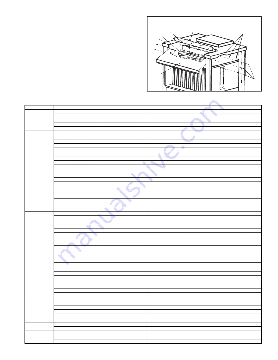
Loosen Screws
Remove
Screws
Tube Baffle Holddown Plate
Rear Baffle
Front
Baffle
Tube
Baffle
FIGURE 50 - Remove "V" Baffles to Clean Inner Surface
of Heat Exchanger Tubes
Indoor, Gravity Vent Models XE/HXE (See FIGURE 50)
1) Remove the screws (the number varies depending on unit size)
along the bottom of the front baffle and the three on each end.
Slide the front baffle out of the furnace.
2) Remove the screws that attach the tube baffle hold-down plate to
the rear flue baffle.
3) Pull the "V" baffles out of the heat exchanger.
All Models
- Clean the inner surfaces of the heat exchanger from be-
neath using the brush to "scrub" the tube walls to remove any accumu-
lated dust, rust and/or soot. Clean the "V" tubes and re-assemble the
heat exchanger and the furnace.
Check the furnace for proper operation.
41. Troubleshooting
Troubleshooting the System
TROUBLE
PROBABLE CAUS E
REMEDY
1.
No power to the furnace.
1.
Turn on power, check supply fuses or circuit breaker.
2.
No 24-volt power to venter relay.
2.
Turn up thermostat, check control transformer output. Check for loose or improper
wire connections.
3.
Venter relay defective.
3.
Replace.
4.
Defective motor or capacitor.
4.
Replace defective part.
1.
M anual valve not open.
1.
Open manual valve.
2.
Air in gas line.
2.
Bleed gas line.
3.
Dirt in p ilot orifice.
3.
Remove and clean with compressed air or solvent (do not ream).
4.
Gas pressure too high or too low.
4.
Adjust supp ly pressure. (See Paragraph 11).
5.
Kinked pilot tubing.
5.
Replace tubing.
6.
Pilot valve does not open.
6.
If 24 volt available at valve, replace valve.
7.
No spark:
7.
a)
Loose wire connections
a)
Be certain all wires connections are solid.
b)
Transformer failure.
b)
Be certain 24 volts is available.
c)
Incorrect spark gap.
c)
M aintain spark gap at 7/64".
d)
Spark cable shorted to ground.
d)
Replace worn or grounded spark cable.
e)
Spark electrode shorted to ground.
e)
Replace pilot if ceramic spark electrode is cracked or grounded.
f)
Drafts affecting pilot.
f)
M ake sure all panels are in place and tightly secured to prevent drafts at pilot.
g)
Ignition control not grounded.
g)
M ake certain ignition control is grounded to furnace chassis.
h)
Faulty ignition controller.
h)
If 24 volt is available to ignition controller and all other causes have been eliminated,
replace controller.
8.
Optional lockout device interrupting control circuit by above causes.
8.
Reset lockout by interrupting control at thermostat.
9.
Faulty combustion air proving switch.
9.
Replace combustion air proving switch.
10.
Activated blocked vent switch (indoor sy stem)
10.
Correct venting problem. Reset switch.
1.
M anual valve not open.
1.
Open manual valve.
2.
M ain valve not operating.
2.
a)
Defective valve.
a)
If 24 volt is measured at valve connections and valve remains closed, rep lace valve.
b)
Loose wire connections.
b)
Check and tighten all wiring connections.
3.
Ignition control does not power main valve.
3.
a)
Loose wire connections.
a)
Check and tighten all wiring connections.
b)
Flame sensor grounded. (Pilot lights - spark continues)
b)
Be certain flame sensor lead is not grounded or insulation or ceramic is not cracked.
Replace as required.
c)
Gas pressure incorrect.
c)
Adjust gas p ressure. (See Paragraph 11.)
d)
Cracked ceramic at sensor.
d)
Replace sensor.
e)
Faulty ignition controller.
e)
See Paragraph 25. If all checks indicate no other cause, replace ignition controller.
Do
not
attempt to repair the ignition controller. This device has no field replaceable parts.
f)
Poor microamp signal
f)
Adjust pilot regulator
1.
Dirty filters in blower system..
1.
Clean or replace filters.
2.
Incorrect manifold pressure or orifices.
2.
Check manifold pressure (See Paragraph 11).
3.
Cycling on limit control.
3.
Check air throughp ut (See Paragrap h 13).
4.
Improper thermostat location or adjustment.
4.
See thermostat manufacturer's instructions.
5.
Belt slipping on blower
5.
Adjust belt tension
6.
Fan control improperly wired
6.
Connect as per wiring diagram.
7.
Defective fan control.
7.
Replace fan control.
8.
Blower set for too low temperature rise.
8.
Slow down blower or increase static pressure.
1.
Circuit op en
1.
Check wiring and connections.
2.
Fan Control inoperative
2.
Replace fan control.
3.
Fan control improperly wired
3.
Connect as per wiring diagram.
4.
Contactor inop erative
4.
Replace contactor.
5.
Defective motor.
5.
Replace motor.
1.
M otor overload device cycling
1.
Check motor load against motor rating p lace. Replace motor or overload device.
2.
3-phase motor rotating in opposite direction
2.
Interchange two legs of supply connections.
1.
Improper motor p ulley adjustment
1.
See instructions on air throughput (See Paragraph 13).
2.
Improper static pressure on duct system
2.
Adjust dampers in duct system.
3.
Low voltage
3.
Check power supp ly.
Pilot lights; main
valve will not open.
Pilot will not light.
(Venter operating
on power-vented
models.)
Venter motor will
not start.
Motor cuts out on
overload
Motor will not run
No heat (Heater
operating.)
Motor turns on and
off while operating


