34
I-EEDU (02-21) 150492-A
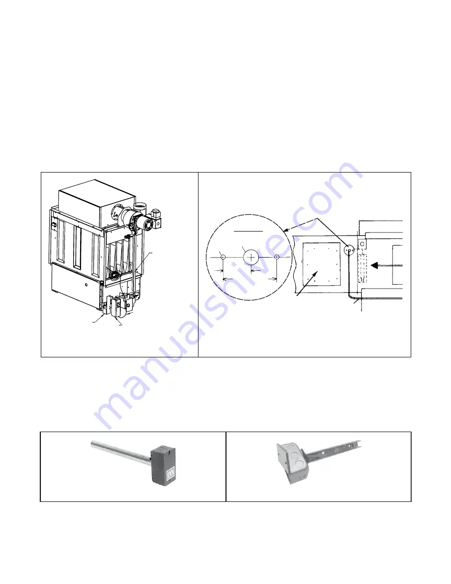
Figure 25. Installing Capillary Sensor Bulb in Discharge Ductwork (Option AG3)
Option AG8, AG9, or AG15: Discharge Air Temperature Sensor Installation
The discharge air sensors shown in
require field-installation in the discharge ductwork . Electronic modulation
options AG8 and AG9 include a sensor and mixing tube and makeup air option AG15 (two-stage valve with remote
ductstat) include a box and sensor holder (PN 115850) . Install the sensor in the ductwork as follows .
FIELD-INSTALLED OPTIONS—CONTINUED
Discharge Air Temperature Sensor Installation—Continued
Option AG3: Discharge Air Temperature Sensor Installation—Continued
4 . Select ductwork location so that minimum length of capillary tubing will be inside ductwork . Follow hole pattern
shown in
, DETAIL B to drill holes in ductwork .
5 . Remove ductwork access panel (see
6 . Remove sensor bulb from bracket and push sensor through 1/2-inch hole . While reaching through access hole,
use retaining clip to reinstall sensor to bracket .
7 . Slide gasket (cut slit) and hole retainer plate over capillary tubing . With gasket next to ductwork, install hole
retaining plate and secure using field-supplied sheet metal screws .
8 . Close ductwork access panel .
Shipping
Angle -
Remove
before
attaching
ductwork.
Ductstat Bracket
- Option AG3
Ductstat -
Option AG3
Ductstat Capillary with
sensing bulb attached
inside the furnace. To
connect ductwork, remove
the bulb with the bracket.
(Save bracket and clip.)
1/2” Diameter
1/8” Dia
3/4”
(19mm)
1-1/2” (38mm)
Capillary Tubing
to Ductstat
Airflow
Hole Pattern
Access
Panel
DETAIL A
DETAIL B
Figure 26. Discharge Air Temperature Sensor
DETAIL A: OPTIONS AG8 AND AG9
DETAIL B: OPTION AG15


