Form 465, Page 36
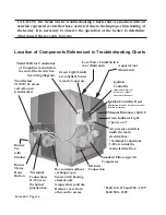
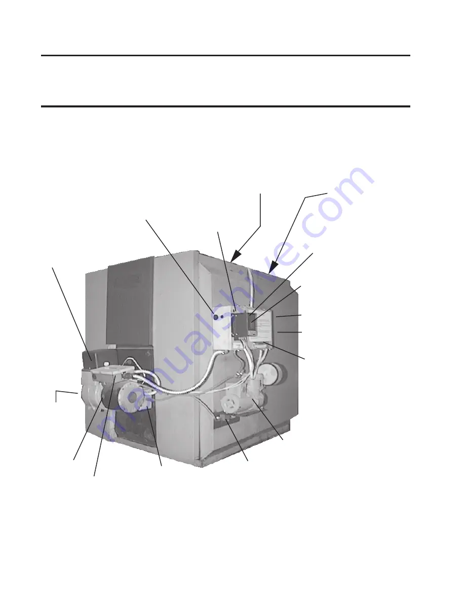
Location of Components Referenced in Troubleshooting Charts
Air pressure switch is
inside the main
electrical box.
*Terminal Connections
1-10 are inside the
main electrical box.
Green Indicator Light
(”power on”)
Manual Disconnect Switch
Oil Inlet
Connection
*Terminal
Connections
11-18 are in
the burner
junction box.
Standard Piston-type Air
Compressor
Box contains oil heat
exchanger (pre-
heater) with heating
element and
temperature controls.
Remove cover from
other end to access.
Burner
Motor
Reset
Button
Burner
Tee
with
Strainer
CAUTION: The items on the Troubleshooting Charts that are marked with an
asterisk represent events that have occurred due to the improper functioning of
the heater. It is necessary to observe the operation of the heater to determine
what caused these events to occur.
*RAB 140, 235 and 350 - 115V
RAB 500 - 230V
Transformer
(NOTE: To access
cad cell, open
transformer.)
Model RAB for Canada has
a 10 amp fuse mounted on
the end of the electric box.
See wiring diagram.
Green Light: Limits
are satisfied; heater
is ready to operate.
Ignition Controller Reset
(illustration may not be same as actual;
location is similar)
Ignition
Controller
(illustration may not
be same as actual;
location is the same)
Low-Water Cutoff Switch
(not illustrated)
Aquastat (not
illustrated)


