background image

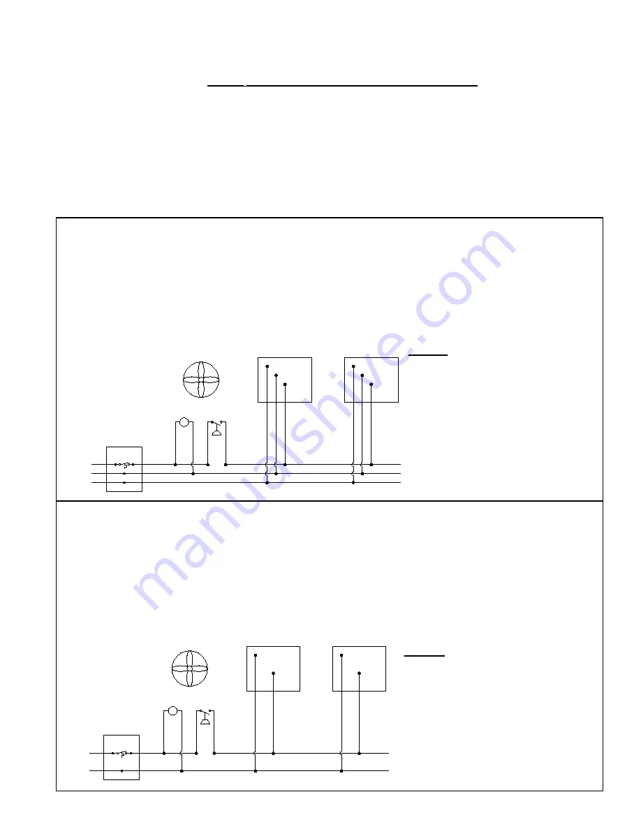
FIGURE 6A - With 120 VAC DIRECT SPARK IGNITION (DSI) SINGLE-STAGE CONTROLS

•  Electrical supply: 120 VAC - 60 Hz - 1 Phase.

•  Maximum total heater current draw: 0.14 Amps.

•  Total heater power consumed: 16.8 VA (16.8W).

•  3-wire field service required.

•  Field wiring having a minimum temperature rating of at least 302°F (150°C) shall be used and supply circuit 

wiring shall have a minimum size of 16 AWG (1.0mm2).

FIGURE 6B - With 24 VAC DIRECT SPARK IGNITION (DSI) SINGLE-STAGE CONTROLS

•  Electrical supply: 24 VAC - 60 Hz or 50 Hz - 1 Phase.

•  Maximum total heater current draw: 0.66 Amps.

•  Total heater power consumed: 15.9 VA (15.9W).

•  2-wire field service required.

•  Field wiring having a minimum temperature rating of at least 302°F (150°C) shall be used and supply circuit 

wiring shall have a minimum size of 16 AWG (1.0mm2).

GND

(-)

(+120)

GGS

BK

BK

GGS

VR*

SW*

MV*

W

W

  120 VAC DSI HEATER ELECTRICAL SUPPLY AND THERMOSTAT WIRING*


LEGEND


(+120) = 120 VAC Supply Voltage 

(-

(-)       = Supply Neutral 

GND   = Earth Ground 

MV*    = Mechanical Ventilation* 

VR*    = Ventilation Relay* 

SW*   = Ventilation Interlock Switch* 


                  (normally opened)


GGS   = Green Ground Screw 


                   (inside control box)


W       = White Wire – Neutral

BK      = Black Wire – 120 VAC call for heat

Thermostat

Heater 1

Heater 2

GND

(+24)

GGS

BL

BL

GGS

VR*

SW*

MV*


 24 VAC DSI SINGLE-STAGE HEATER ELECTRICAL SUPPLY AND THERMOSTAT WIRING*


LEGEND


(+24) = 24 VAC Supply Voltage 

GND  = Earth Ground 

MV*   = Mechanical Ventilation* 

VR*   = Ventilation Relay* 

SW*  = Ventilation Interlock Switch*  

                  (normally opened) 


GGS  = Green Ground Screw 


                   (inside control box)


BL     = Blue Wire – 24 VAC call for heat


Thermostat

Heater 1

Heater 2

7.2 Electrical 

Requirements 

by Voltage and 

Control Types

More specific electrical requirements may vary depending on whether the unit is sin-

gle-stage (115V), single-stage (24V), or two-stage (24V). Select the information that 

applies to the unit being installed. 

NOTES


common to FIGURES 6A, 6B, and 6C (page 12):

• 

* Mechanical ventilation interlock is required when all combustion air is provided 

by a mechanical air supply system.

• 

#10 ring terminal is required for ground service conductor (by others) to attach to 

green ground screw on heater.

• 

The heater control is extremely polarity sensitive and the heater will cycle on 

and off erratically if the electrical supply is not wired correctly. Have a qualified 

electrician check that the electrical supply circuit is properly grounded and that the 

electrical supply polarity is correct.

• 

All components and wiring illustrated are field-supplied. 

Form I-RIH, P/N 131793R8, Page 11 

Summary of Contents for RIH

Page 1: ...ervicing this equipment FOR YOUR SAFETY If you smell gas 1 Open Windows 2 Don t touch electrical switches 3 Extinguish any open flame 4 Immediately call your gas supplier The use and storage of gasoline or other flammable vapors and liquids in the vicinity of this appliance is hazardous WARNING Gas fired appliances are not designed for use in hazardous atmospheres containing flammable vapors or co...

Page 2: ...ructions and in compliance with all codes and requirements of authorities having jurisdiction DANGER These infrared heaters are operated without venting Comply with ventilation requirements in Paragraph 2 2 page 5 Model RIH and RIHV series heaters SHOULD NOT BE USED in the following applica tions Enclosed swimming pool areas Areas with contaminated atmospheres Outdoor applications Residential appl...

Page 3: ...ese codes are available from CSA Information Services 1 800 463 6727 Local authorities having jurisdiction should be consulted before installation is made to verify local codes and installation procedure requirements All electrical wiring including electrical grounding must be in accordance with the National Electric Code ANSI NFPA No 70 latest edition or in Canada the Canadian Electrical Code Par...

Page 4: ...be provided to shut off the burner and prevent its operation until the required clearance has been re established 1 0 General cont d 1 4 Installation Codes cont d Applies to Units Mounted at a 5 Angle Distance from the Wall Maximum Distance Between Heater Rows With Standard Reflector With Parabolic Reflector Option DM2 RIHN 30 8 ft 2 4M 5 ft 1 5M 90 ft 27 4M RIHL 50 RIHN 60 12 ft 3 7M 9 ft 2 7M 10...

Page 5: ...small exhausters should be distributed over the roof areas and interlocked with various heating zones Local codes may permit the use of humidistat control to remove water vapor and products of combustion Humidistat settings will typically be in the 40 to 55 relative humidity range Fresh air intake openings are typically located high on the building sidewalls at or above the level of the heaters On...

Page 6: ... will not cause combustible materials or materials in storage to attain a temperature in excess of 150 F 66 C See Hazard Levels page 2 WARNING Under no circumstances should this heater be installed in a combustible atmosphere or in a location where the heater controls can be subjected to ambient temperatures in excess of 150 F 66 C See Hazard Levels page 2 It is recommended that more distance than...

Page 7: ... ANSI Z233 1 NFPA 54 The stated clearance to combustibles represents a surface temperature of 90 F 50 C above room temperature Building materials with low heat tolerance such as plastic vinyl siding canvas tri ply etc may be subject to degradation at lower temperatures It is the responsibility of the installer to assure that adjacent materials are protected from degradation ANSI Z83 19 It is recom...

Page 8: ...hains along the length of the long chains 5 Check to be sure unit is level Crimp all S hooks closed A B C and D FIGURE 4 Chain Hanging Instructions Using either the chains and S hooks in Option UE1 chain and S hooks in Option UE2 or field provided chain and S hooks 5 0 Suspending the Unit cont d 3 8 10mm all thread rods for rigid mount 200 91kg working load chain for chain mount 1 4 6 3mm diameter...

Page 9: ...y only be used if permitted by local code It is recommended that either the piping or the mounting be flexible to prevent fatigue failure from vibration and or thermal expansion A first stage pressure regulator is required when gas supply pressure exceeds 14 35cm w c If a pressure regulator is required be sure that it is installed in the gas line with the arrow indicating gas flow pointing in the ...

Page 10: ... group of heaters can be controlled by a thermostat or manual switch Total load of all heaters must be considered in determining the required contact rating of the controlling thermostat or switch General Requirements The electrical supply wiring to the heaters using 120 VAC or 24 VAC must be installed in accordance with local codes or the National Electric Code ANSI NFPA 70 latest edition IMPORTA...

Page 11: ...e 120 VAC call for heat Thermostat Heater 1 Heater 2 GND 24 GGS BL BL GGS VR SW MV 24 VAC DSI SINGLE STAGE HEATER ELECTRICAL SUPPLY AND THERMOSTAT WIRING LEGEND 24 24 VAC Supply Voltage GND Earth Ground MV Mechanical Ventilation VR Ventilation Relay SW Ventilation Interlock Switch normally opened GGS Green Ground Screw inside control box BL Blue Wire 24 VAC call for heat Thermostat Heater 1 Heater...

Page 12: ... Blue Wire 24 VAC call for LOW heat R on heater Red Wire 24 VAC call for HIGH heat Use 18 4 solid class 2 thermostat cable between heater and thermostat with a maximum length of 125 feet 38m Heater 1 Heater 2 FIGURE 7A 120 VAC Direct Spark Ignition Electrical Connection Diagram Greem Ground Screw GGS W 1 BK 1 W 2 R 1 W 3 BK 2 1 2 burner R 2 3 4 burner O O Y G 120 GND G R 1 W 2 BK 1 W 1 Y Combinati...

Page 13: ...aving a temperature rating of at least 302 F 150 C and a minimum size of 16 AWG 1 0mm2 24 VAC 60 or 50 Hz 1 Phase Heater Maximum Current Draw 0 96 Amps Total Heater Power Consumed 23 1 VA FIGURE 7C 24 VAC 2 STAGE DIRECT SPARK IGNITION ELECTRICAL CONNECTION DIAGRAM Wire Colors BK Black G Green O Orange R Red W White Y Yellow field wiring Combination Gas Valve CGV Flame Sensor FS Flame Sensor FS Spa...

Page 14: ...the burner fail to light or flame is not detected during the first trial for ignition period the combination gas valve is de energized and the controller starts the 15 second inter purge sequence before another ignition trial After 15 seconds the controller begins two 2 more ignition trials If the burner fails to light after the third trial the controller will de energize the gas valve and go into...

Page 15: ...e heater should be free of objects that may overheat or prevent infrared energy from reaching desired area Post signs indicating maximum stacking height under or near heater Heater may be angle mounted only as specified See Paragraph 5 0 Heater must be level and suspended according to instructions in Paragraph 5 0 Be sure there are no gas or electric lines above or below the heater Adequate ventil...

Page 16: ...s a 24 120 volt thermostat that can be used to control 1 5 units This thermostat can also be used to control the exhaust fan circuit Thermostat Option CL82 is a 24 volt 2 stage digital thermostat that can be used with Option AG2R for automatic control of 1 5 units Parabolic Reflector Option DM2 The addition of the parabolic reflector increases the infrared intensity pattern while decreasing the sc...

Page 17: ...0kPa or less blow off all accumulated dust and dirt Blow air over the ceramic tile avoiding gasket material between tile and alternately into the venturi several times in succession Be careful not to damage gasket material between ceramic tiles Damaging the material between the tiles could lead to burner flashback E D C B A G F LEGEND Symbol Item Description A Gas manifold B Gas orifice C Venturi ...

Page 18: ...o electrical earth ground 3 Provide electrical earth ground 4 Electrical supply line voltage neutral polarity reversed 4 Correct electrical supply polarity 5 Heat on pilot flame sensor insufficient 5 Clean pilot check pilot orifice and alignment No pilot 1 Gas line contains air 1 Purge air from gas line 2 Pilot line orifice or passage blocked 2 Check and clean See Paragraph 11 1 3 Pilot solenoid v...

Page 19: ...t defective 2 Replace thermostat 3 High heat valve not opening 3 Replace high heat valve 2 Stage transition from high heat to low heat does not happen 1 Ambient temperature has not reached low heat zone of thermostat 1 Allow time for ambient temperature to reach low heat zone of thermostat Check thermostat manufacturer s instructions 2 Thermostat defective 2 Replace thermostat 3 High heat valve no...

Page 20: ...______ Model No ______________ Serial No _____________________Date of Installation ____________ SPECIFIC INSTALLATION NOTES i e Location Clearances Amps Gas Pressure Temperature Voltage Warranty etc _______________________________________________________________________________ _______________________________________________________________________________ _________________________________________...

Reviews: