18
SSCBL-RPBL-IOM (10-22) 149159-C
INSTALLATION—CONTINUED
Field-Installation of Cooling Coil Cabinet and Downturn Plenum—Continued
Using the parts shipped inside the cooling coil cabinet (refer to
), follow the instructions to connect the coil
cabinet to the furnace . In addition to normally-required tools, a driver extension, a hammer, and a bar or short length
of 2 × 4 will be required . Silicone caulking must be field-supplied .
1 . After blower/furnace packaged system is in place on roof curb or mounting rails, remove lifting lugs on discharge
end of system using 9/16 wrench or socket .
2 . Lift cooling coil cabinet and position it with inlet side next to discharge opening of furnace . Remove lifting lugs
on cooling coil cabinet .
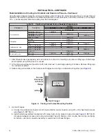
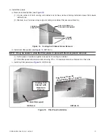
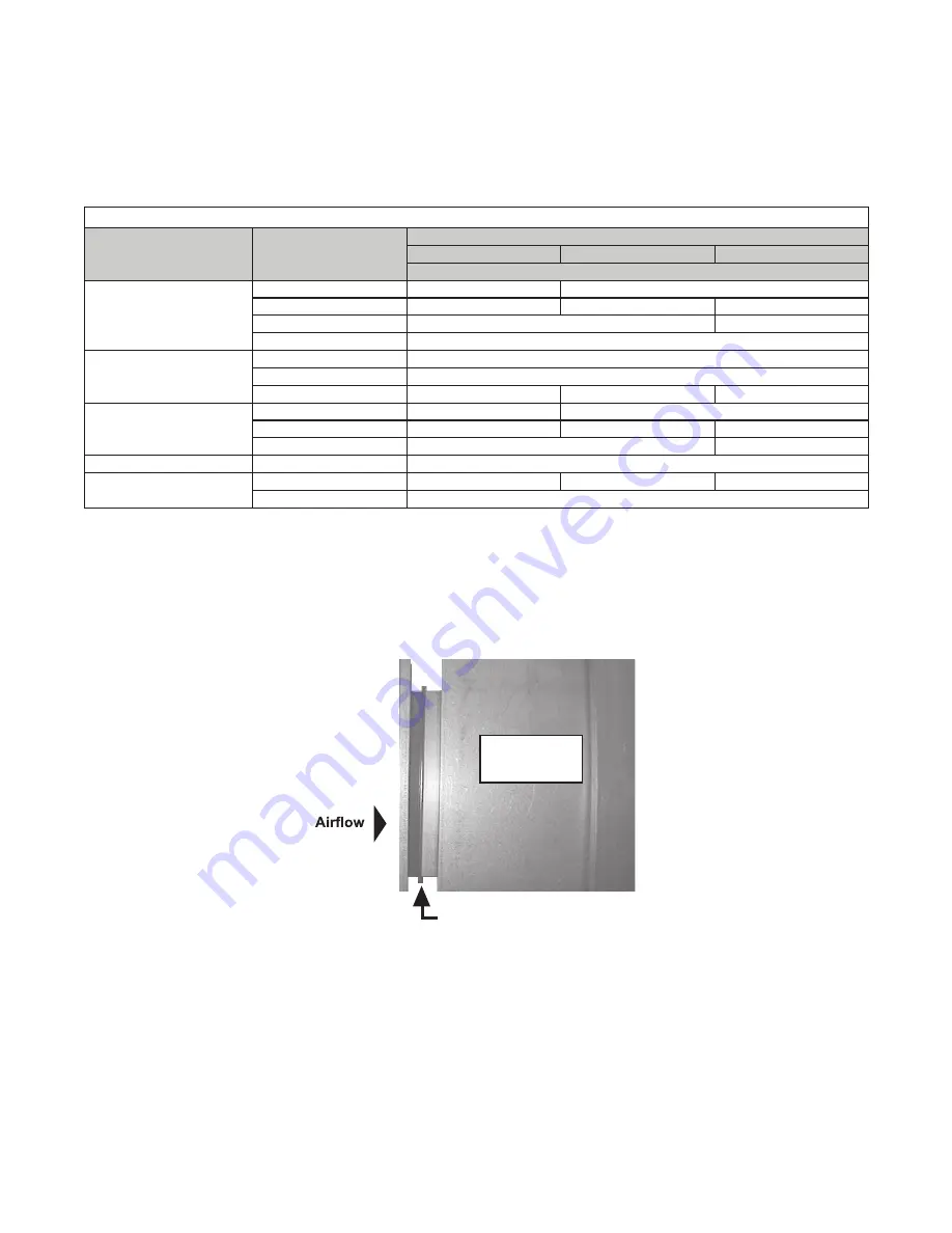
3 . Slide cooling coil cabinet so that furnace duct flanges and cooling coil cabinet butt together (see
) .
Figure 8. Cooling Coil Cabinet Mounting Position
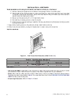
4 . Join duct flanges:
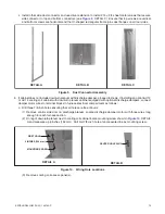
a . Connect one side duct connector to both top and bottom duct connectors using #14 × 3/4 sheet metal screws
(see
, DETAIL A) .
b . Install partially-assembled connectors with screw holes in top piece at open side (see
into space between furnace and cooling coil cabinet . Tap with hammer—first on side, then on top, and lastly
on bottom—until duct connector assembly is seated over both duct flanges .
Table 13. Cooling Coil Cabinet Factory-Supplied Components
Component
Description
Unit Size
500, 600
700, 1050
400, 800, 1200
PN (Quantity)
Duct connector
Top/bottom, 36-inch
106338 (2)
—
Top/bottom, 41-1/2-inch
—
106339 (2)
—
Top/bottom, 47-inch
—
106340 (2)
Side, 19-1/2-inch
106395 (2)
Filler panel
Left side
172357 (1)
Right side
172358 (1)
Top
172362 (1)
172363 (1)
172364 (1)
Rubber gasket strip
3/32 × 1-1/8 × 53-7/8
103608 (1)
—
3/32 × 1-1/8 × 59-3/8
—
103609 (1)
—
3/32 × 1-1/8 × 64-7/8
—
106310 (1)
Insulation
1 × 42 × 9
172546 (2)
Sheet metal screw
#10 × 1/2
11813 (24)
11813 (25)
11813 (26)
#14 × 3/4
105171 (8)
Furnace
Discharge
with Duct
Flange
Duct Flanges
Cooling Coil
Cabinet


