19
SSCBL-RPBL-IOM (10-22) 149159-C
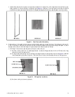
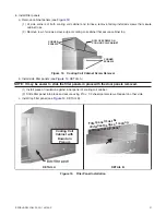
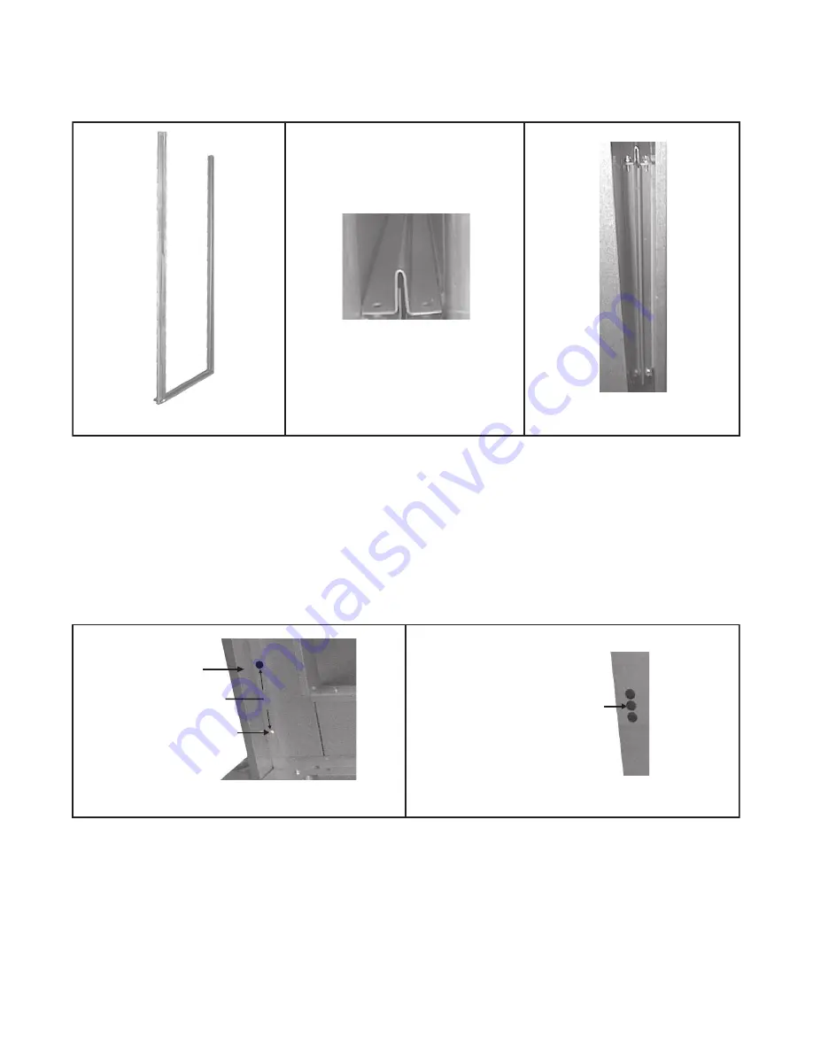
c . Install other side duct connector and use driver extension to install #14 × 3/4 sheet metal screws that secure
side connector to top and bottom connectors (see
, DETAIL C) . Ensure that top screws are vertical
and bottom screws are horizontal and that U-shaped rectangular frame joins duct flanges on all four sides .
Figure 9. Duct Connector Assembly
5 . If cabinet does not include downturn plenum with discharge damper, proceed to step 6 . If installing an option AU12
or AU14 cooling coil cabinet with downturn plenum cabinet equipped with optional discharge dampers, connect
damper motor wires to terminal blocks in furnace electrical compartment as follows:
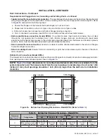
a . Drill three 7/8-inch holes ensuring that all holes are free of burrs:
(1) Remove control side door on discharge plenum . Locate discharge damper motor with three wires long
enough to reach furnace section .
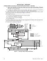
(2) On leg of downturn plenum next to cooling coil cabinet locate mounting screw shown in
A and measure up 6 inches (152 mm) . Drill first 7/8-inch hole at same center line as mounting screw .
Figure 10. Wiring Hole Locations
(3) Remove cooling coil access panel(s) .
DETAIL A
DETAIL B
DETAIL C
MOUNTING SCREW
6 INCHES (152 mm)
FIRST HOLE
CENTER HOLE PLUG
DETAIL A
DETAIL B


