26
SSCBL-RPBL-IOM (10-22) 149159-C
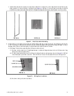
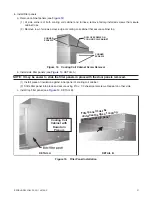
DETAIL A: SENSOR AND MIXING TUBE
DETAIL B: SENSOR HOLDER
INSTALLATION—CONTINUED
Duct Connections—Continued
Discharge Air Temperature Sensor Installation—Continued
3 . Secure sensor in ductwork:
a . Position of sensor in duct is also important—mixing tube shown in
, DETAIL A is 12 inches (305 mm)
long and holder shown in
, DETAIL B extends 9-3/16 inches (233 mm) into ductwork .
b . For units with sensor holder, turn holder so that element is shielded from direct airflow and will sense air
temperature as it flows through holes in holder .
c . At selected ductwork location, mark diamond-shaped hole—approximately 1
×
1 inch (25
×
25 mm—required
for sensor holder or round hole required for mixing tube and cut hole no larger than necessary .
d . For units with sensor and mixing tube, slide mixing tube (see
, DETAIL A) into ductwork and attach
sensor .
e . For units with sensor holder, push element into clip in holder (see
, DETAIL B), slide holder into
ductwork, and position holder so that it shields sensor from direct airflow . Secure box portion of holder to
ductwork using four field-supplied #6 sheet metal screws .
Figure 17. Discharge Air Temperature Sensor and Holder
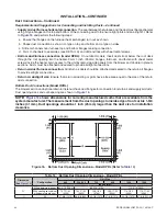
f . For units with option AG39 or AG41:
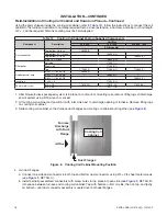
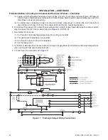
(1) Sensor is factory-installed in cabinet leg (see
) . Remove access panel in ductwork adjacent to
control compartment access panel .
(2) Element is retained by either spring clips or cable straps .
(3) Round gasket and metal retaining plate provide airtight seal for capillary and must be removed to remove
element .
Figure 18. Discharge Air Temperature Sensor Location (Options AG39 and AG41)


