51
SSCBL-RPBL-IOM (10-22) 149159-C
Optional Two-Stage Control (Makeup Air Application)
•
On systems with more than one furnace section, there are two methods of achieving multiple-stage makeup air
operation . In addition, for each of these methods, there are two types of control mechanisms . Consult the wiring
diagram on the furnace to identify the optional control system: option AG3, AG4, AG5, AG15, AG17, or AG19 .
• Option AG3 or AG15:
The first method is comparable to the two-stage heating units . Instead of control from a
two-stage room thermostat, the discharge air temperature is monitored and the two-stage gas valve is controlled
by a two-stage ductstat . When the discharge air temperature drops to the setpoint, low fire is energized . If low
fire cannot satisfy the ductstat setting, high fire is energized . As the packaged system may include two or three
furnace sections, and as each section is equipped with a two-stage gas valve, the operation stages increase with
the number of furnace sections . Set the ductstat as indicated in
.
• Option AG4, AG5, AG17, or AG19:
The second method of multiple-stage makeup air operation is applicable only
to systems that include two or three furnace sections . On systems with two furnaces, this optional control system is
identified as option AG4 or AG17 . On packaged systems with three furnace sections, this optional control method
is identified as option AG5 or AG19 . Each furnace in the package is equipped with a single-stage gas valve . The
single-stage gas valves are staged by two-stage ductstats . The furnaces are staged in sequence . This concept
will achieve two-stage control on packaged systems with two furnaces and three-stage control on systems with
three furnaces . Set the ductstat as indicated in
.
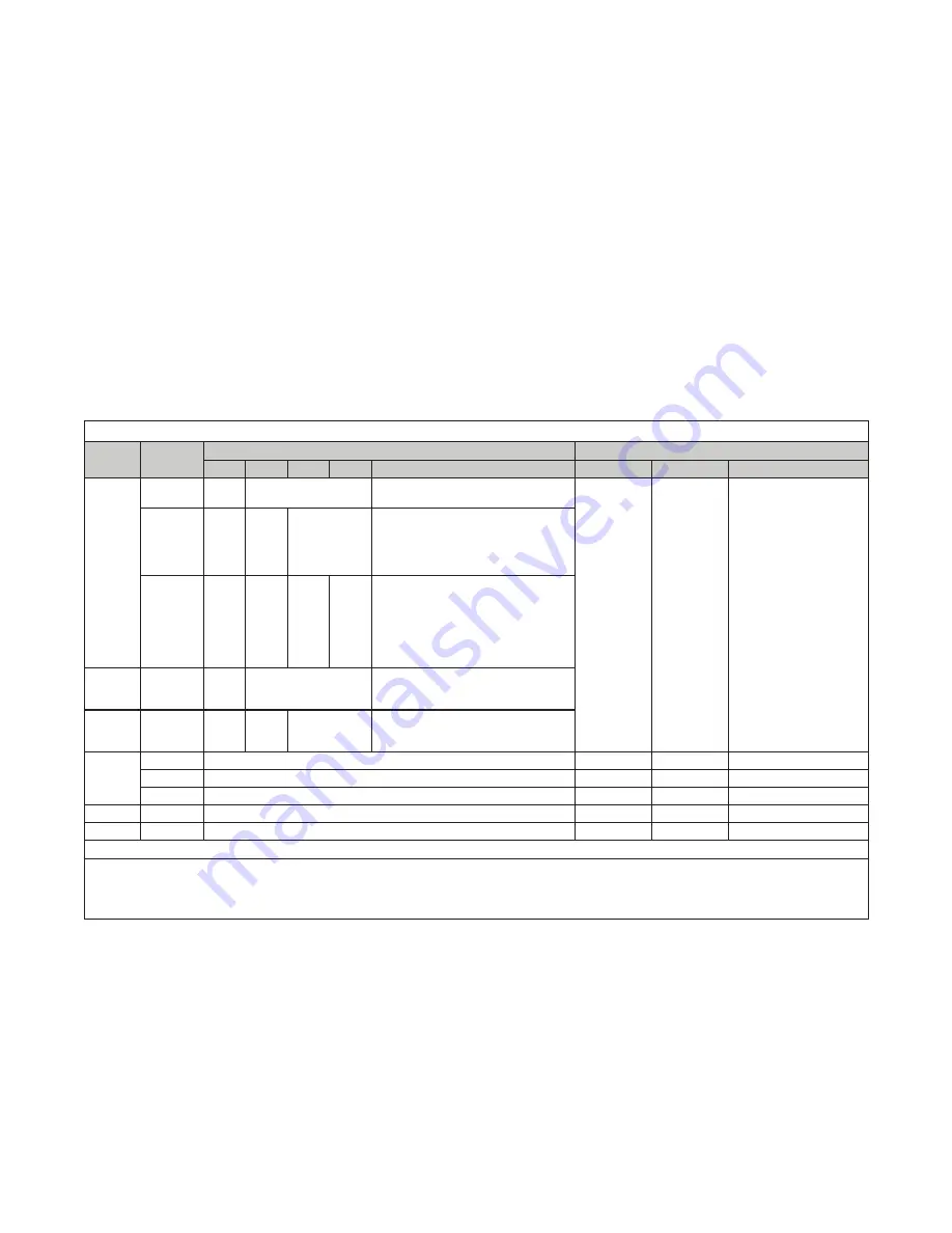
Table 27. Recommended Settings for Two-Stage Makeup Air Control
Option
No. of
Furnaces
Ductstat Setting
*
Temperature Selector Setting
**
1st
2nd
3rd
4th
Staging Sequence
Setpoint
Differential
Stage Adder Offset
AG3
1
70°F
—
66°F high stage
→
70°F low stage
→
74°F shutdown
—
—
—
2
70°F
64°F
—
60°F high stage (both furnaces)
→
64°F low stage (furnace 2)
→
68°F shutdown (furnace 2)
→
70°F low stage (furnace 1)
→
74°F shutdown (furnace 1)
3
70°F
66°F
62°F
—
58°F high stage (all furnaces)
→
62°F low stage (furnace 3)
→
66°F shutdown (furnace 3),
low stage (furnace 2)
→
70°F shutdown (furnace 2),
low stage (furnace 1)
→
74°F shutdown (furnace 1)
AG4
2
70°F
—
66°F full rate (both furnaces)
→
70°F shutdown (furnace 1)
→
74°F shutdown (furnace 2)
AG5
3
70°F
64°F
—
60°F full rate (both furnaces)
→
68°F shutdown (furnace 3 and 2)
→
74°F shutdown (furnace 1)
AG15
1
—
74°F
8°F
4°F
2
—
74°F
14°F
10°F, 6°F, 4°F
3
—
74°F
16°F
10°F, 8°F, 8°F, 4°F, 4°F
AG17
2
—
74°F
8°F
4°F
AG19
3
—
74°F
10°F
6°F, 6°F
*
Set each ductstat control in furnace order .
**
Adjust the setpoint and the differential of the temperature selector (Johnson #A350) . Adjust the offset potentiometer on each of the stage
adder modules (Johnson #S350) . Follow the manufacturer’s instructions provided .
IMPORTANT:
Set the temperature selector and each
stage adder module to HEAT . Follow the wiring diagram to obtain proper sequencing .
Operation:
The differential setting and offset degrees
allow the controls to adapt to any adjustment in temperature selection (50–130°F) .
Optional Ductstat with Capillary Tubing (Option AG3, AG4, or AG5)
The makeup air control options with the complete two-stage ductstat installed in the heater discharge use a ductstat
(see
, DETAIL A) with an adjustable range between 0° and 100°F with a fixed differential of 2-1/2° . Due
to different CFM settings and outside air temperatures, the average downstream outlet temperature may not match
the ductstat setting exactly . After the installation is complete, re-adjust the setpoint of the ductstat(s) to achieve the
desired average discharge air temperature . In general, makeup air applications are usually adjusted to discharge
an outlet air temperature between 65°F and 75°F .


