57
SSCBL-RPBL-IOM (10-22) 149159-C
• Burner orifices:
Heaters are shipped with orifices of proper size and type for gas specified . Natural gas units do
not require a carryover orifice .
•
During regular service, check the main burner ports, the carryover assemblies, and the orifices for cleanliness .
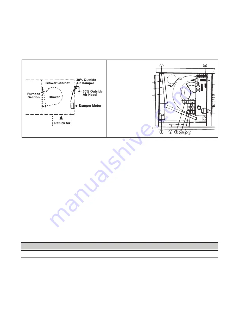
Dampers and Damper Controls
For information on damper control options (see
), refer to the wiring diagram provided with the unit . To
adjust dampers, refer to the
section .
Figure 42. Damper Controls
Pressure Null Switch
The pressure null switch used to control outside air dampers in inlet air option AR23 is a Dwyer #1640-0 with a range
of 0 .01–0 .20 IN WC . It is shipped separately for-field installation—refer to the manufacturer’s installation instructions
included with the switch . The pressure null switch is a diaphragm-operated differential pressure switch used in
makeup air applications to control building pressure . It maintains a selected positive or negative pressure setpoint
by changing the amount of outside air being introduced to the building through the modulating outside air dampers .
As more pressure is required in the building, the pressure null switch activates the damper motor driving the outside
air damper towards the full open position and the recirculated air damper towards the closed position . Conversely,
as less pressure is required, the switch drives the dampers in the opposite direction . To adjust the switch, refer to
Pressure Null Switch Adjustment
section .
Dirty Filter Switch
The optional dirty filter pressure switch is used to provide warning to the user by energizing an indicator light on
an optional remote console . The light indicates that the filters are in need of cleaning or changing . The adjustable,
single-pole/normally-open differential switch closes when an increase in pressure differential above the setpoint, is
sensed across the filter bank . The dirty filter switch is located in the furnace section . To adjust the dirty filter switch,
refer to the
Dirty Filter Switch Adjustment
section .
OPERATION
⚠ WARNING ⚠
To ensure safety, follow the lighting instructions located on the outlet box cover.
30% Outside Air Hood and Damper
Options (AR6 or AR7)
100% Outside Air
and 100% Return Air
Damper Options
1.
Damper Motor
2.
Return Air Damper
3.
Potentiometer
4.
Potentiometer
5.
Mixed Air Controller
6.
Warmup Control
7.
Outside Air Damper
8.
Damper Motor
Transformer


