63
SSCBL-RPBL-IOM (10-22) 149159-C
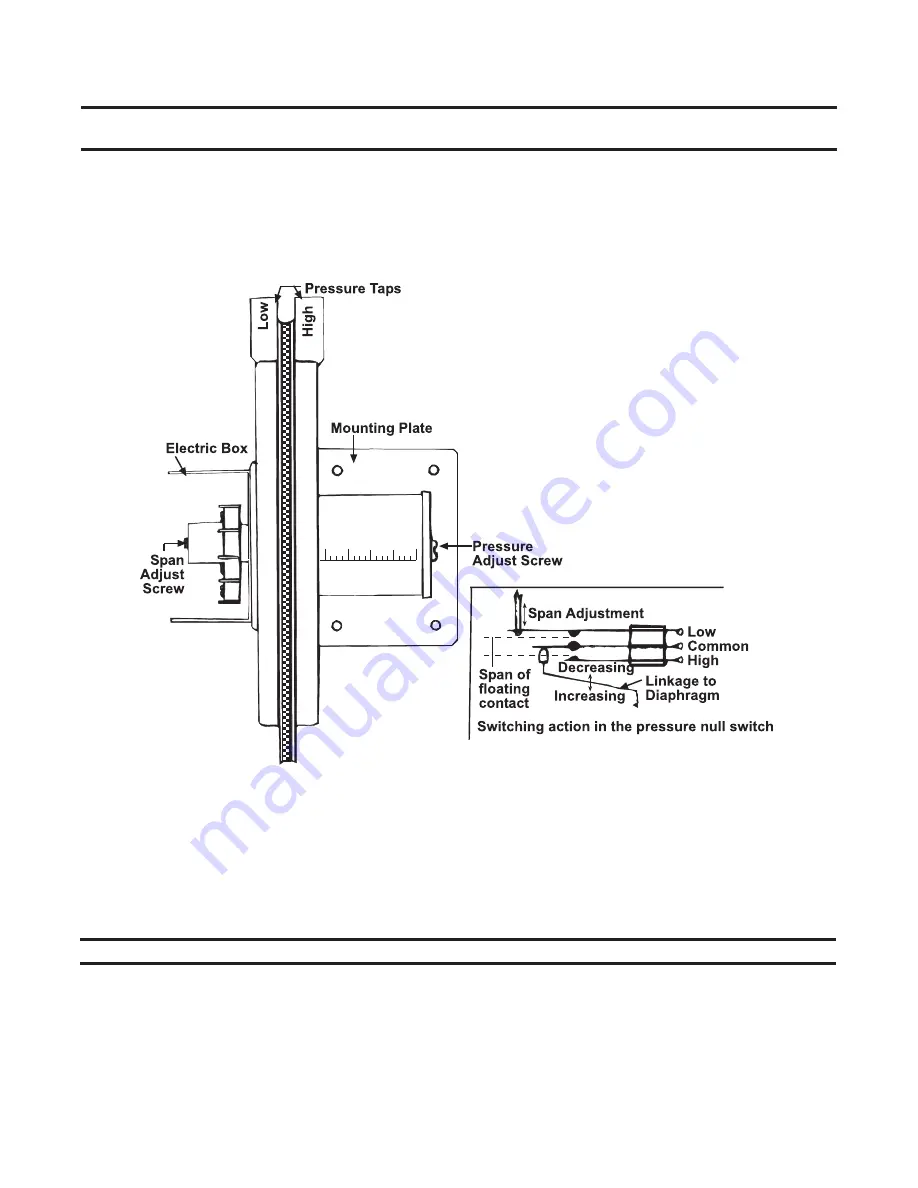
Figure 45. Pressure Null Switch Adjustment
Measure and Adjust Manifold (Outlet) Gas Pressure
Measuring manifold gas pressure cannot be done until the heater is in operation (refer to
section) .
• For natural gas:
When the heater leaves the factory, the combination valve is set so that the outlet gas pressure
of a single-stage valve or high fire of a two-stage valve is regulated to 3 .5 IN WC . Low fire on a two-stage valve
is set to 1 .8 IN WC . Inlet supply pressure to the valve must be a minimum of 5 IN WC or as noted on the rating
plate and a maximum of 14 IN WC .
NOTE: Always check the rating plate for minimum gas supply pressure.
• Minimum natural gas supply pressure:
Requirements vary based on size of burner and the gas control option .
Most units require a minimum of 5 IN WC natural gas as stated above, but sizes 400, 700, 800, 1050, and 1200
with electronic modulation require a minimum of 6 IN WC natural gas supply pressure .
• For propane gas:
When the heater leaves the factory, the combination valve is set so that the outlet gas pressure
of a single-stage valve or high fire of a two-stage valve is 10 IN WC . Low fire on a two-stage valve is set to 5 IN
WC . Inlet pressure to the valve must be a minimum of 11 IN WC and a maximum of 14 IN WC .
Pressure Null Switch Adjustment
NOTE: IMPORTANT: To eliminate shipping damage to the pressure null switch contacts, the manu-
facturer reduced the span adjustment to zero before shipping.
The span should be adjusted prior to using the pressure null switch (see
) as follows:
1 . If switch has been installed, disconnect vent tube so that switch is in neutral position .
2 . Remove electrical box cover and, while observing contacts, turn span adjustment screw slowly in clockwise direction .
3 . Continue turning adjustment screw until you are able to see gaps between common and both low and high
contacts—minimum gap provides greatest sensitivity—wider gap provides lower sensitivity .


