15
SSCBL-RPBL-IOM (10-22) 149159-C
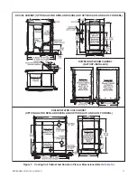
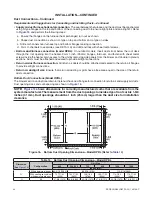
Figure 6. Suspension of Model SSCBL (Refer to
)
Mounting (Model SSCBL)
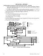
Lift the unit using a suitable hoist and spreader bars and
s
et it on the rails . Leave the ends open underneath for
ventilation .
Mounting (Model RPBL)
⚠ CAUTION ⚠
IMPORTANT: To prevent damage from wind blown rain and capillary action, the top surface of the
curb MUST be sealed using 1/4-inch × 1-1/4-inch sealant tape or two 1/4-inch beads of suitable
sealant.
NOTE: If the system includes an outside air hood, a cooling coil cabinet, or an evaporative cooling
module, install it after the unit is in place. Options AU2, AU3, AU11, AU12, AU13, and AU14 are not
factory-installed and must must be lifted to the roof separately from the packaged system, set on
the roof curb, and attached to the furnace.
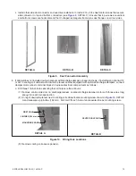
1 . Apply furnished 1/4-inch × 1-1/4-inch foam sealant tape or two 1/4-inch beads of suitable sealant to top surface
of curb, making good butt joints at corners .
2 . Lift unit using suitable hoist and spreader bars and
s
et it on curb or rails . If set on rails, leave ends open underneath
for ventilation .
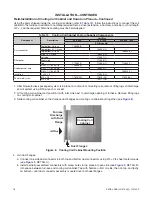
Top View of Curb Cap Assembly
Suspension Point Dimensions
G
F
H
Airflow
58-25/32 (1493)
3/4
(19)
3/4
(19)
DETAIL A
DETAIL B
Table 11. SSCBL Suspension Dimensions
Dimension
)
Unit Size
400
500, 600
700
800
1050
1200
Inches (mm)
F
59-9/16 (1513)
48-9/16 (1233)
54-1/16 (1373)
59-9/16 (1513)
54-1/16 (1373)
59-9/16 (1513)
G
54-3/8 (1381)
43-3/8 (1102)
48-7/8 (1229)
54-3/8 (1381)
48-7/8 (1229)
54-3/8 (1381)
H
*
27-3/32 (688)
53-3/32 (1352)
79-7/32 (2012)
*
Does not apply to a system with a field-installed cooling coil cabinet (option AU2 or AU3) .


