RFX-RMT-II Dual Band
LAST REV: April 2008
13
Operator’s Manual
RF ExtremeCare: 866.732.0113
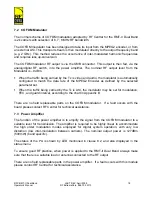
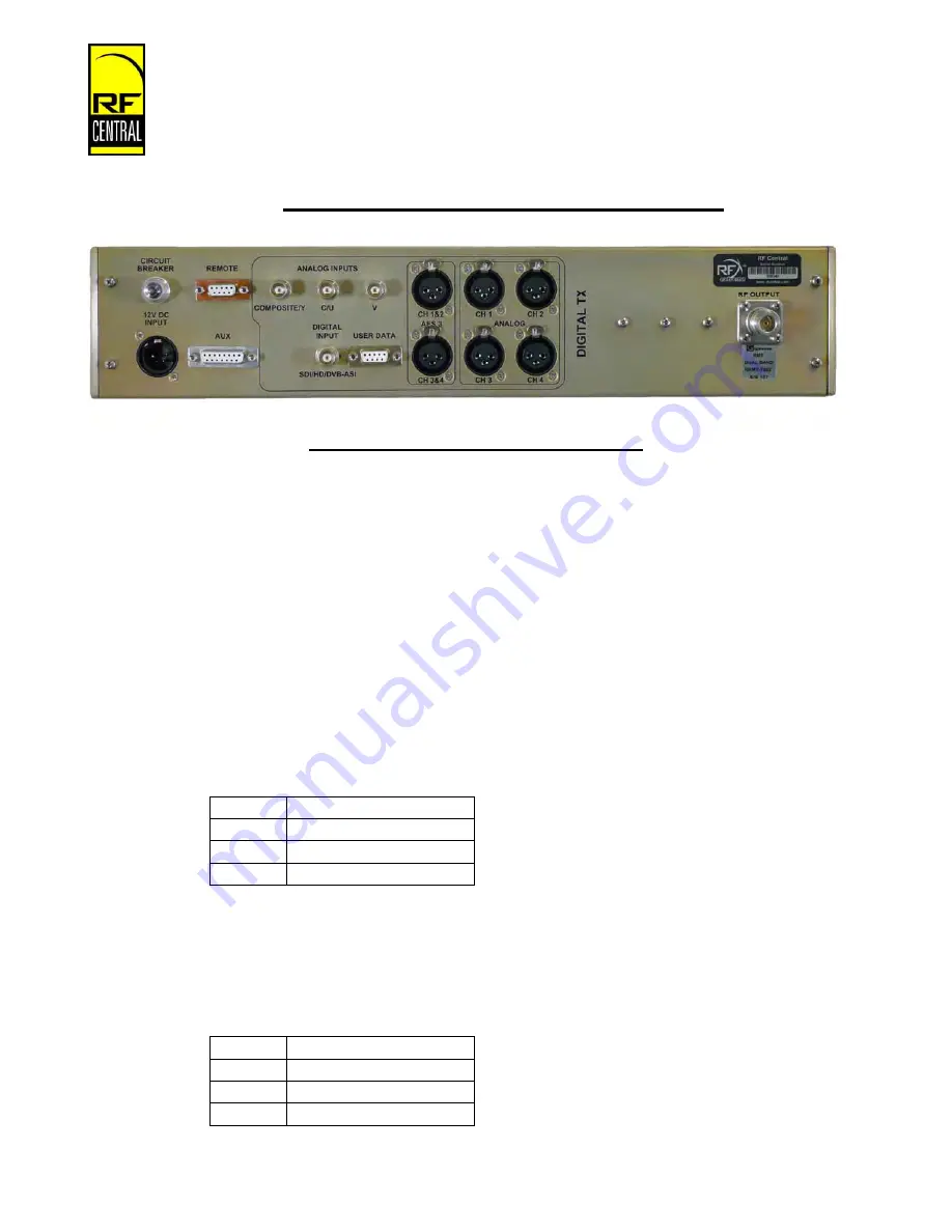
6 REAR PANEL CONNECTIONS
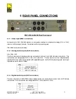
RMT-II DUAL BAND Rear Panel layout
6.1.1 Video
input
(BNC connectors)
Connectors for SD / HD SDI digital, or composite analog or component analog (Y/C or YUV)
video or ASI transport stream. Selected via front panel keypad.
75
Ω
BNC connectors (female)
6.1.2 Analog Audio inputs (XLR connectors)
Line / Mic Hi Z
The four channels of analog audio are connected via four 3 pin XLR female connectors. The
connectors are designated Ch1, Ch2, Ch3 and Ch4. These inputs can be independently
selected for Line or Mic level inputs with adjustable gain, via the front panel keypad, and input
impedance set to 600 or 50K
Ω
.
Pin
1 Analog
Ground
2
Ch1/ A / Left +ve
3
Ch1/ A / Left -ve
6.1.3 Digital Audio inputs (XLR connectors)
The two channels of AES EBU stereo digital audio are connected via two 3pin XLR female
connectors. The connectors are designated Ch1 / Ch2 and Ch3 / Ch4.
Pin
1 Ground
2 Live/
+ve
3 Return/
-ve


