background image


RFX-RMT-II Dual Band 

LAST REV: April 2008   

30 

Operator’s Manual 

RF ExtremeCare: 866.732.0113 


DIGITAL TX
CH 1        2.11250 MHz
64QAM      ½       1/32
? /?   FOR  MAIN  MENU

STATUS         1/2
PA                   O N
SYNTH LOCK  YES


CURRENT OPERATIONAL STATE

RMT HD/SD – OPS M ENU – 

ASI M ODE

CONFIG           1/1
ASI DATA RATE
18.096257 Mbit/s
ASI TYPE NO RMAL

STATUS         2/2
ASI IN             NO
TS                   O K

MAIN MENU

CH/FREQ

CH/FREQ
CH 1   7.11250 GHZ

CH/FREQ
CH 12   7.2650 GHZ

CH/FREQ
MAN   7.2  00 GHZ

5

E

ASI OPTIONS

M ODULATION  M ODE

G UARD INTERVAL

ASI/MPEG

ASI

MPEG

B

B

A = CURSO R LEFT

B = CURSO R RIG HT

    = INCREASE DIG IT VALUE

    = DECREASE DIGIT VALUE

CODE RATE

QPSK

16QAM

64QAM

1/2

2/3

3/4

1/4

1/8

1/16

1/32

E

E

5/6

7/8

ASI TYPE

REBRO

NORMAL


Summary of Contents for RFX-RMT-II Dual Band SD/HD

Page 1: ...AST REV April 2008 1 Operator s Manual RF ExtremeCare 866 732 0113 RFX RMT II Dual Band SD HD Rack Mounted Transmitter OPERATOR S MANUAL Copyright 2008 RF Central Need help Contact Technical Support 866 732 0113 866 RFC 0113 ...

Page 2: ...e Monitoring and Control 14 6 1 7 User data future option 15 6 1 8 Aux 15 7 CIRCUIT DESCRIPTIONS 16 7 1 Audio Video Encoder 16 7 2 COFDM Modulator 18 7 3 Power Amplifier 18 7 4 Power amplifier control PCB 19 7 5 Front panel 19 8 CONFIGURING THE TRANSMITTER 20 8 1 Control Mode 20 8 2 Status and Local remote Monitoring 20 8 3 Top level Menu 20 8 3 1 Initialization Menu 21 8 3 2 Top level and Current...

Page 3: ...5 Relay outputs 27 8 8 6 Cable equalizer 27 8 8 7 Channel plan 27 8 8 8 Software Inventory 27 8 8 9 Remote options 27 9 PREPARING FOR OPERATION 32 9 1 The RMT II Dual Band Transmitter 32 9 1 1 Antennas 32 9 1 2 Checks 32 9 2 The Receiving Equipment 33 9 3 Transmitter Receiver tests 33 10 SYSTEM REMOTE MONITORING AND SETUP 34 11 APPENDIX A MPEG Encoder SD Parameter Sets 35 12 APPENDIX B MPEG Encode...

Page 4: ...y be present Users are strongly recommended to return any equipment that requires RF servicing to RF Central WARNING GaAs BeO Hazard Certain components inside the equipment contain Gallium Arsenide and Beryllium Oxide that are toxic substances While safe to handle under normal circumstances individual components must not be cut broken apart incinerated or chemically processed In the case of Beryll...

Page 5: ...orld and are from time to time re issued with revised guidelines For RF Central use a maximum power density limit w of 1w m is to be applied when calculating minimum safe working distances Refer to Appendix A Important Note It must be remembered that any transmitting equipment radiating power at frequencies of 100 kHz and higher has the potential to produce thermal and athermal effects upon the hu...

Page 6: ...h the person subjected to the RF radiation may be unaware of and has no control over the radiation energy received The uncontrolled environment conditions can arise even in the best regulated operations and for this reason the limits defined for the uncontrolled environment have been assumed for the RF Central recommended limit Documents a and b also show the RF power density guidelines to be freq...

Page 7: ...ther with 4 audios analog AES digital or SDI embedded The unit may be switched between SD and HD encoding profiles optional The unit may be controlled in three ways by remote control RS232 485 by front panel key pad and LCD display comprehensive functions and by front panel switches frequency and power only MPEG encoding parameters are set from 16 pre set conditions with an additional user presets...

Page 8: ... Selectable to less than 2 frames minimum Tx to Rx Video Input SDI HD SMPTE 292M 299M SDI SD SMPTE 259M 272M Analog Composite and YUV YC Component video Audio Input Digital HD SDI embedded Digital SD SDI embedded 1 x AES3 stereo Analog 1 x stereo 2 x mono inputs mic line selectable ASI Data Input ASI transport stream 188 204 byte automatic selection of burst byte or packet mode Aux Data Input Aux ...

Page 9: ...T II Dual Band LAST REV April 2008 9 Operator s Manual RF ExtremeCare 866 732 0113 4 OVERVIEW OF RMT II DUAL BAND TRANSMITTER SHF Power Amplifier Motherboard Encoder Module Front Panel Module Modulator Module ...

Page 10: ...e modulator module 3 Modulator module This module accepts the digital transport stream from the encoder module and uses digital COFDM modulation techniques to produce a digital RF signal at the required RF frequency 4 Power Amplifier This module accepts the analog or digital RF signal at a level of 10dBm nominal and amplifies the signal to a level of 500 mW 27dBm nominal 5 Power amplifier control ...

Page 11: ... amber On Off Switch Down for Off up for On On Off Power Amplifier Down Transmitter output power amplifier OFF Up Transmitter output power amplifier ON This function can also be controlled via the push buttons and RMT II Dual Band menus and via remote control Channels 2 and 7GHz Thumb wheels 0 9 Selects the pre set RF channel This function can also be controlled via the push buttons and RMT II Dua...

Page 12: ... Band is functioning correctly A flashing green light indicates that the RMT II Dual Band is functioning correctly but that no video or ASI signal is present at the input connector A red light indicates that the unit has an alarm condition Local LED Indicates whether the RMT II Dual Band is in local control mode key pad or switches or remote control RS232 485 menu Green light local control amber l...

Page 13: ...ectors Line Mic Hi Z The four channels of analog audio are connected via four 3 pin XLR female connectors The connectors are designated Ch1 Ch2 Ch3 and Ch4 These inputs can be independently selected for Line or Mic level inputs with adjustable gain via the front panel keypad and input impedance set to 600 or 50KΩ Pin 1 Analog Ground 2 Ch1 A Left ve 3 Ch1 A Left ve 6 1 3 Digital Audio inputs XLR co...

Page 14: ...type female 6 1 6 Remote Monitoring and Control Connector Type 9 way D type female Remote Control and Monitoring interface selectable to RS 232 or RS 485 RS 232 CONNECTIONS RS 485 CONNECTIONS Pin Direction Direction 1 Not Used Not Used 2 Data Tx Out from Unit Data Tx ve Out from Unit 3 Data Rx Into Unit Data Rx ve Into Unit 4 Not Used Not Used 5 Ground Ground 6 Not Used Data Tx ve Out from Unit 7 ...

Page 15: ...NS Pin 1 Not Used Not Used 2 Not Used Not Used 3 User Data User Data ve 4 Not Used Not Used 5 Ground Ground 6 Not Used Not Used 7 Not Used User Data ve 6 1 8 Aux Connector Type 15 way D type female Auxiliary relays and band selection Pin 1 Not Used 2 Not Used 3 Relay 1 On 4 Relay 1 Off 5 Relay 2 On 6 Relay 2 Off 7 Band select 7GHz 5 to 24 8 Band select 0 volt 9 Ground 10 Ground 11 Relay 1 common 1...

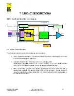
Page 16: ...al Motherboard PA control PCB 7 1 Audio Video Encoder The Encoder board consists of the following main functions SDI to Digital de serializer Converts the SMPTE 259M C serial digital video input to an 8 bit parallel digital video bus Analog to Digital Video Converter 10 bit over sampling ADC Takes either composite video 75 Ω 1v p p CVBS YC or YUV inputs in either PAL NTSC format and converts to an...

Page 17: ...i directionally predicted frames 4 2 2 Only in conjunction with motion compensation thus low data rates down to 4 Mbps can be achieved The encoder includes special modes which are optimized for low delay latency The encoding parameters are loaded into the encoder at power up These are selected from one of the preset encoder memories See 8 4 6 and Appendix B ASI routing As an alternative to the int...

Page 18: ...selected parameter set When the traffic being carried by the Tx is ASI the modulator may be set for modulation FEC and guard interval according to the chart in Appendix B There are no field replaceable parts on the COFDM modulator If a fault occurs with the board please contact RF Central for technical assistance 7 3 Power Amplifier The function of the power amplifier is to amplify the signal from...

Page 19: ...s board An I2 C two wire interface is used to communicate with all other intelligent devices within the unit This carries the command data and reads back status data from all boards within the unit All configuration parameters video settings audio settings MPEG encoder parameters frequencies etc are held on this board This allows the ability to change other boards within the unit without the loss ...

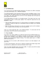
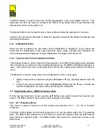
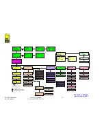
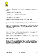
Page 20: ...s voltage selects the 2 GHz band See paragraph 6 1 8 To change the control mode refer to paragraph 8 5 1 8 2 Status and Local remote Monitoring The red green status LED on the front panel indicates the condition of the RMT II Dual Band If a fault or warning exists the LED will indicate Red and the Status menu will indicate the nature of the fault warning During initialization of the unit the Statu...

Page 21: ...f the RMT II Dual Band and indicates the Tx frequency Channel number or Manual frequency the MPEG COFDM parameters in use The screen also has a bar graph which shows the output power offset according to 8 4 9 The B button is used to show other current parameters this is in two parts Status three screens selected using the B followed key indicates alarms from the unit Config four screens selected u...

Page 22: ...UV analog or SDI digital or internal test color bars In HD mode the unit can accept HD SDI or internal color bars test signal In the event that BARS is selected a sub menu allows ALT BARS 75 or 100 BARS to be selected 8 4 4 Video definition This menu allows the encoding to be selected between HD and SD modes This menu is not available on units preset to SD only operation 8 4 5 Modify USER PSET In ...

Page 23: ...tter to be stored and loaded this includes channel frequency definition video and audio inputs etc A total of 4 Presets may be accessed additionally a Default factory setting is provided 8 4 9 Output power The output power of the transmitter may be set 0 to 12dB below the nominal maximum output power Separate presets are provided for 2 and 7GHz bands A calibrated dB offset is provided plus a bar g...

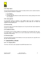
Page 24: ...tores the value and returns to the main menu 8 5 3 No video action The action of the unit in the event of no video at the input can be set to Black screen Power amplifier muted Color bars 8 5 4 Video Format PAL NTSC The video format may be selected PAL or NTSC 8 5 5 PID editor PIDs used by the encoder and entered into the DVB transport stream may be individually assigned 8 5 6 Spectrum invert The ...

Page 25: ...ns to the equipment For short cable runs 25 meters the equalizer should be switched off 8 5 10 Channel Plan The pre set 2 GHz RF channel plan assigned to the 10 way thumb wheel may be selected to the old or new BAS plan 8 5 11 Software Inventory The firmware versions currently installed in the transmitter can be obtained from this menu The serial numbers of the firmware can be used in discussions ...

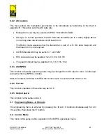
Page 26: ...s not required COFDM bandwidth may be set to 6 7 or 8 MHz FEC code rate may be selected 1 2 2 3 3 4 5 6 7 8 The guard interval may be selected 1 4 1 8 1 16 1 32 8 6 3 ASI MPEG This function allows the operating mode may be changed from ASI input to video audio input using the internal MPEG encoder After the mode is switched to MPEG the control menu converts to that shown in 8 4 8 6 4 Presets This ...

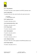
Page 27: ...e set to No action Power amplifier muted 8 8 3 Spectrum invert The action is the same as 8 5 6 8 8 4 Band selection front rear The action is the same as 8 5 7 8 8 5 Relay outputs The action is the same as 8 5 8 8 8 6 Cable equalizer The action is the same as 8 5 9 8 8 7 Channel plan The action is the same as 8 5 10 8 8 8 Software Inventory This menu is the same as the equivalent in the MPEG Operat...

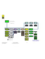
Page 28: ...CH 1 2 11250 GHZ CH FREQ CH 12 2 2650 GHZ CH FREQ MAN 2 2 00 GHZ 5 MAIN MENU AUDIO AUDIO INPUT ANALOGUE AUDIO 1 5 AUDIO 2 AUDIO 3 AUDIO 4 DIGITAL ANALOGUE EMBEDDED LINE MIC AUDIO LEVEL 0 0DB AUDIO 1 SELECT INPUT AUDIO 1 SET LEVEL E E E VIDEO INPUT SDI SDI YUV 5 YC CVBS BARS 75 100 ALT BARS E ENCODER PSET 1 PSET 8 ASI MPEG MPEG ASI MPEG E B B A CURSOR LEFT B CURSOR RIGHT INCREASE DIGIT VALUE DECREA...

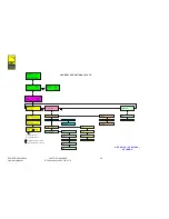
Page 29: ... PROG CHANNELS PROG CHANNEL Ch 1 2 30000GHz PROG CHANNEL Ch 10 2 4 600GHz PROG CHANNEL Ch 10 2 70000GHz E 5 A MOVE TO DIGIT ON LEFT B MOVE TO DIGIT ON RIGHT INCREASE DIGIT VALUE DECREASE DIGIT VALUE BLK SCREEN MUTE PA BARS NTSC PAL PID EDITOR PID PMT 32 PID PCR 8190 PID VID 300 AUDIO 1 200 AUDIO 2 201 USER 202 ENCODER FPGA TDME 0102 06 ENCODER TDME 0101 03 MOD SYNTH TDZU 0801 03 REMOTE OPTIONS E R...

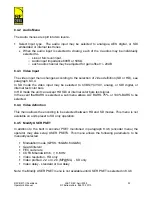
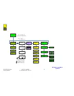
Page 30: ...NU ASI MODE CONFIG 1 1 ASI DATA RATE 18 096257 Mbit s ASI TYPE NORMAL STATUS 2 2 ASI IN NO TS OK MAIN MENU CH FREQ CH FREQ CH 1 7 11250 GHZ CH FREQ CH 12 7 2650 GHZ CH FREQ MAN 7 2 00 GHZ 5 E ASI OPTIONS MODULATION MODE GUARD INTERVAL ASI MPEG ASI MPEG B B A CURSOR LEFT B CURSOR RIGHT INCREASE DIGIT VALUE DECREASE DIGIT VALUE CODE RATE QPSK 16QAM 64QAM 1 2 2 3 3 4 1 4 1 8 1 16 1 32 E E 5 6 7 8 ASI...

Page 31: ...OFTWARE INVENTRY E FRONT PANEL TDFP 0164 01 MOTHERBOARD RMMB 0102 01 PSU MONITOR TDMN 0401 ENG MENU PROG CHANNELS PROG CHANNEL Ch 1 2 30000GHz PROG CHANNEL Ch 10 2 4 600GHz PROG CHANNEL Ch 10 2 70000GHz E 5 A MOVE TO DIGIT ON LEFT B MOVE TO DIGIT ON RIGHT INCREASE DIGIT VALUE DECREASE DIGIT VALUE NO ACTION MUTE PA ENCODER FPGA TDME 0102 06 ENCODER TDME 0101 03 MOD SYNTH TDZU 0801 03 REMOTE OPTIONS...

Page 32: ...as are used to uplink ground to air or on board linking HX series antennas offer increased gain and directivity FBA fan beam antennas offer increased gain and 90 degree sector coverage Parabolic antennas offer the highest gain and longest operation range Full details are given in the RF Central Antennas data sheets 9 1 2 Checks The transmitter may be powered from an external DC PSU or through the ...

Page 33: ... are necessary ensure that the connectors are compatible and of good quality to avoid problems at site Check that the receiving antenna receiver interfaces are clean and free from dust and other unwanted materials If tripods are to be used to mount the equipment make sure that some means of securing the tripod or of weighting it down is provided Gusty wind conditions may put installations at risk ...

Page 34: ...32 0113 10 SYSTEM REMOTE MONITORING AND SETUP The RMT II Dual Band may be operated under remote control using RS 232 or RS 485 Information for the set up of the remote control interface is given in paragraph 8 5 12 For details of the remote control protocol please contact RF Central ...

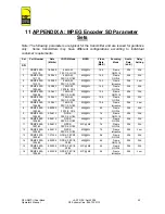
Page 35: ... Std 5 PBMP 3000 1004 08 12 0641 16 QAM FEC1 2 G1 32 422 ML 10 4 Frame GOP 16 256 Std 6 PBMP 3000 1005 08 12 0641 16 QAM FEC1 2 G1 32 422 ML 10 4 Frame GOP 4 256 Std 7 PBMP 3000 1006 08 12 0641 16 QAM FEC1 2 G1 32 MP ML 10 4 Frame Intraslice 256 Low 8 PBMP 3000 1002 68 9 95293 16 QAM FEC1 2 G1 4 422 ML 8 3 Frame GOP 4 256 Std 9 PBMP 3000 1005 02 9 04812 QPSK FEC3 4 G1 32 422 ML 7 4 Frame GOP 16 25...

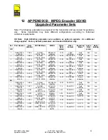
Page 36: ...9 fps Field Intraslice 384 Low 5 PBMP 3000 5006 0A 18 096 16 QAM FEC3 4 G1 32 MP H14 L Intraslice 16 00 1080i 25 29 fps Frame Intraslice 384 Std 6 PBMP 3000 5013 10 18 096 64 QAM FEC1 2 G1 32 MP H14 L Intraslice 16 00 1080i 25 29 fps Frame Intraslice 384 Std 7 PBMP 3000 5006 11 24 128 64 QAM FEC2 3 G1 32 MP H14 L Intraslice 22 00 1080i 25 29 fps Frame Intraslice 384 Std 8 PBMP 3000 5014 10 18 096 ...

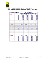
Page 37: ...6 1 8 1 4 1 2 6 03 5 85 5 53 4 98 2 3 8 04 7 81 7 37 6 64 3 4 9 05 8 78 8 29 7 46 5 6 10 1 9 76 9 22 8 29 7 8 10 6 10 2 9 68 8 71 16 QAM 1 32 1 16 1 8 1 4 1 2 12 1 11 7 11 1 9 95 2 3 16 1 15 6 14 7 13 3 3 4 18 1 17 6 16 6 14 9 5 6 20 1 19 5 18 4 16 6 7 8 21 1 20 5 19 4 17 4 64 QAM 1 32 1 16 1 8 1 4 1 2 18 1 17 6 16 6 14 9 2 3 24 1 23 4 22 1 19 9 3 4 27 1 26 3 24 9 22 4 5 6 30 2 29 3 27 6 24 9 7 8 ...

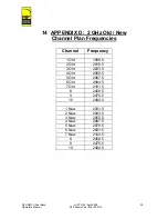
Page 38: ...DIX D 2 GHz Old New Channel Plan Frequencies Channel Frequency 1 Old 1999 0 2 Old 2016 5 3 Old 2033 5 4 Old 2050 5 5 Old 2067 5 6 Old 2084 5 7 Old 2101 5 8 2458 5 9 2475 5 10 2492 0 1 New 2031 5 2 New 2043 5 3 New 2055 5 4 New 2067 5 5 New 2079 5 6 New 2091 5 7 New 2103 5 8 2458 5 9 2475 5 10 2492 0 ...

Reviews: