RF-83UP
Shenzhen RF-star Technology Co., Ltd.
Page 26 of 35
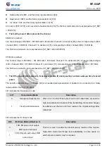
bit5, bit4 and bit3 indicates the wireless wake-up time
bit3 bit2 bit1
Wake-up Time (ms)
Description
0
0
0
250 (by default)
The transceiver modules work in normal mode. The delay time is invalid
and can be any value.
The transmitting module works in the wake-up mode and will
continuously transmit the call code for the corresponding time.
The receiving module works in low-power mode. This time refers to the
listening interval time (wireless wake-up) of the receiver and can only
receive data from the transmitting module working in wake-up mode.
0
0
1
500
0
1
0
750
0
1
1
1000
1
0
0
1250
1
0
1
1500
1
1
0
1750
1
1
1
2000
bit2 is reserved unused.
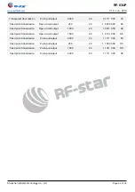
bit1 and bit0 indicate the transmit power.
bit1
bit0
Transmit Power
(Approximate Value)
Description
0
0
30 dBm (by default)
The external power supply must provide more than 250 mA current
output capability. And ensure that the power supply ripple is less than
100 mV. It is not recommended to use smaller power transmission,
because its power utilization efficiency is not high.
0
1
27 dBm
1
0
24 dBm
1
1
20 dBm
7.2.3 Examples
Examples: 1. Normal mode, 2. Push-pull output, 3. Wireless wake-up time of 500 ms, 4. Transmit power of 30 dBm. It
needs to be expressed as follows: (bit 2 is reserved unused and default as 0)
[1 001 0 00], converted to hexadecimal = [48]
The above can be expressed as: [AT_SET=03,E8,25,17,48]. What it means: All set parameters are saved after powered
off. The parameters are modified to: module address of 1000, serial parity bit of 8N1, baud rate of 19200, air rate of
19.2k, channel of 6 (frequency 868) or channel of 15 (frequency 915), normal mode, push-pull output, wake-up time of
500 ms and transmit power of 30 dBm.

