background image


RF-83UP 

www.szrfstar.com

                                                                                                                                                    V1.3 - Jun., 2019 

Shenzhen RF-star Technology Co., Ltd.                                                                                                                   

Page  27  of  35


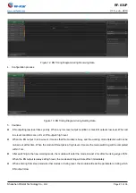
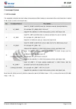
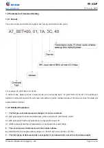
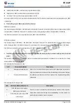
Here are some common commands: 

1. 

The second group of data: address 

Address Number 

In Hex 

Address 1 

00 01 

Address 2 

00 02 

Address 3 

00 03 

Address 30 

00 1E 

Address 31 

00 1F 

Address 32 

00 20 

Address 60 

00 3C 

Address 61 

00 3D 

Address 62 

00 3E 

Address 101 

00 65 

Address 102 

00 66 

Address 103 

00 67 


2. 

The third group of data: serial parity bit, baud rate, air rate 

Serial Parity Bite 

Baud Rate (bps) 

Air Rate (bps) 

In Binary 

In Hex 

8N1 

9600 

0.3k 

00 011 000 

18 

8N1 

9600 

2.4k 

00 011 010 

1A 

8N1 

9600 

19.2k 

00 011 101 

1D 

8N1 

19200 

0.3k 

00 100 000 

20 

8N1 

19200 

2.4k 

00 100 010 

22 

8N1 

19200 

19.2k 

00 100 101 

25 

8N1 

115200 

0.3k 

00 111 000 

38 

8N1 

115200 

2.4k 

00 111 010 

3A 

8N1 

115200 

19.2k 

00 111 101 

3D 

8O1 

9600 

0.3k 

01 011 000 

58 

8O1 

9600 

2.4k 

01 011 010 

5A 

8O1 

9600 

19.2k 

01 011 101 

5D 

8O1 

115200 

0.3k 

01 111 000 

78 

8O1 

115200 

2.4K 

01 111 010 

7A 

Summary of Contents for 42UH

Page 1: ...RF 83UP SX1276 868 MHz 915 MHz LoRa Module Version 1 3 Shenzhen RF star Technology Co Ltd Jun 19 2019...

Page 2: ...H Half hole IPEX 25 40 3 Half hole 433 27 10 Contact Me RF 43UP SMA 24 43 Half hole 433 27 10 RF 43SH Half hole 25 40 DIP 433 27 10 Contact Me SX1276 RF 82UH Half hole IPEX 16 26 Half hole 868 915 18...

Page 3: ...utput power 30 dBm 14 dBm high efficiency PA and an integrated PA Programmable bit rate up to 300 kbps High sensitivity down to 149 dBm Bullet proof front end IIP3 11 dBm Excellent blocking immunity L...

Page 4: ...f the form of RF 83UP where the fields are defined as follows Figure 2 Part Number Conventions of RF 83UP RF 8 Company Name RF STAR 3 Communication Interface Mode UART TX Power 30 dBm U Frequency Rang...

Page 5: ...iguration and Functions 7 2 1 Module Parameters 7 2 2 Module Pin Diagram 8 2 3 Pin Functions 8 3 Specifications 10 3 1 Recommended Operating Conditions 10 3 2 Handling Ratings 10 3 3 Current Consumpti...

Page 6: ...Detailed Parameters 23 7 2 3 Examples 26 8 Implementation 30 8 1 Hardware Design 30 8 2 Trouble Shooting 31 8 2 1 Unsatisfactory Transmission Distance 31 8 2 2 Vulnerable Module 31 8 2 3 High Bit Erro...

Page 7: ...e up Sleep MCU 20 Figure 11 EN Timing Diagram during Sending Data 20 Figure 12 EN Timing Diagram during Receiving Data 21 Figure 13 EN Timing Diagram during Setting Data 21 Figure 14 Recommended Reflo...

Page 8: ...fault as 0 Crystal 32 MHz Package DIP Package Dimension 43 0 mm x 24 0 mm x 2 5 0 1 mm Antenna SMA connector Operating Humidity 10 RH 90 RH no condensation Storage Humidity 10 RH 90 RH no condensation...

Page 9: ...83UP Pin Name Pin Type Description 1 RES_MCU I Reset pin NC 2 GND P Ground NC 3 SWIM_MCU IO SWIM pin of internal MCU 4 VCC P VCC Power supply pin when flash the firmware 5 S0 I Cooperate with S1 to d...

Page 10: ...UART TX signal 9 EN O Pull the serial port high before sending data and pull low after sending Timed wake up pin pull high when wake up Pull high when module sending data pull low after sending 10 VCC...

Page 11: ...25 90 Human Body Model HBM class2 2000 4000 V Moisture Sensitivity Level 2 Charged Device Model Class 3 500 1000 V 3 3 Current Consumption The current consumption characteristics of this module are ca...

Page 12: ...Shenzhen RF star Technology Co Ltd Page 11 of 35 IDDT Supply current in Transmit mode with impedance matching RFOP 20 dBm on PA_BOOST 120 mA RFOP 17 dBm on PA_BOOST 87 mA RFOP 13 dBm on RFO_LF HF pin...

Page 13: ...ar com V1 3 Jun 2019 Shenzhen RF star Technology Co Ltd Page 12 of 35 4 Application and Layout 4 1 Module Photos Figure 4 Photos of RF 83UP 4 2 Recommended PCB Footprint Figure 5 Recommended PCB Footp...

Page 14: ...PB4 17 SPI1_SCK PB5 18 SPI1_MOSI PB6 19 SPI1_MISO PB7 20 PD4 TIM1_CH2 21 I2C1_SDA PC0 22 I2C_SCL PC1 23 PC2 24 PC3 25 PC4 26 PC5 27 PC6 28 SWIM PA0 U2 STM8151G4 C40 15pF C41 15pF R9 1K 1 2 3 4 5 6 7...

Page 15: ...module to take effect Modifications in sleep mode can be used directly 5 2 Mode Switching 0 for Low Level 1 for High Level 1 Combine high and low levels of S0 and S1 to determine the working mode of t...

Page 16: ...rove system efficiency and reduce power consumption 5 3 Normal Mode Type When S0 0 and S1 0 the module works in normal mode Transmitting The single packet length of wireless data transmitted by the mo...

Page 17: ...receiving module working in the low power mode Therefore the data transmitted in the wake up mode can be received by the module in the normal mode wake up mode and low power mode Receiving Equivalent...

Page 18: ...on format details When entering other modes from sleep mode the module will re configure the parameters During the configuration EN remains low After completion the module outputs high level so it is...

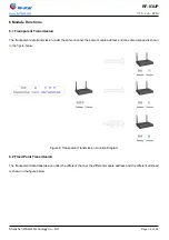
Page 19: ...rent data transmission under the same channel the same module address and the same airspeed is shown in the figure below Figure 8 Transparent Transmission Function Diagram 6 2 Fixed Point Transmission...

Page 20: ...ess and destination channel Listening and broadcasting are exactly the opposite Listening is passive Set the address of the module itself to FF FF and the module can receive the data sent by all modul...

Page 21: ...tes whether any data of the module has not been transmitted through the wireless whether the wireless data has been received but has not been completely transmitted through the serial port or the modu...

Page 22: ...igh level When the EN output in at low level it means that the module is busy and the working mode detection will not be carried out at this time When the module EN output is at high level it means th...

Page 23: ...Supports normal mode wake up mode and sleep mode 3 AT_RSSI Send AT_RSSI in ASCII format the module returns AT_RSSI value hex For example AT_RSSI 2F Supports the operation in normal mode wake up mode...

Page 24: ...response If the input is correct the data just entered will be returned 7 2 2 Detailed Parameters 1 The first group of data represents the type of control command AT_SET represents the control comman...

Page 25: ...he wireless transceiver 0 0 1 2400 0 1 0 4800 0 1 1 9600 by default 1 0 0 19200 1 0 1 38400 1 1 0 57600 1 1 1 115200 bit3 bit2 bit1 means air rate bit3 bit2 bit1 Air Rate bps Description 0 0 0 0 3k Th...

Page 26: ...in decimal is 1F corresponding to 900 channels MHz 931 MHz The first five commands can be expressed as AT_SET A0 03 E8 25 0F 5 The fifth group of data represents transmission mode IO driving method wi...

Page 27: ...bit1 bit0 Transmit Power Approximate Value Description 0 0 30 dBm by default The external power supply must provide more than 250 mA current output capability And ensure that the power supply ripple...

Page 28: ...66 Address 103 00 67 2 The third group of data serial parity bit baud rate air rate Serial Parity Bite Baud Rate bps Air Rate bps In Binary In Hex 8N1 9600 0 3k 00 011 000 18 8N1 9600 2 4k 00 011 010...

Page 29: ...1E 31 931 1F 4 The fifth group of data transmission mode IO driving method wireless wake up time transmit power bit2 is not used and default as 0 Transmission Mode IO Driven Mode Wake up Time ms Trans...

Page 30: ...00 0 00 80 Fixed point transmission Open circuit output 1000 20 1 0 011 0 00 98 Fixed point transmission Open circuit output 1500 20 1 0 101 0 00 A8 Fixed point transmission Push pull output 2000 20 1...

Page 31: ...igital part of module and routed in the Bottom Layer all copper is well grounded 5 Assuming that the module is soldered or placed in the Top Layer it is also wrong to randomly route the Bottom Layer o...

Page 32: ...ffect the communication distance 8 2 2 Vulnerable Module 1 Please ensure the supply voltage is between the recommended values The module will be permanently damaged if the voltage exceeds the maximum...

Page 33: ...times 2 times based on the following reflow soldering profile 4 Temperature profile Reflow soldering shall be done according to the following temperature profile 5 Peak temperature 245 Table 6 Tempera...

Page 34: ...szrfstar com V1 3 Jun 2019 Shenzhen RF star Technology Co Ltd Page 33 of 35 Figure 14 Recommended Reflow for Lead Free Solder 8 5 Optional Packaging Figure 15 Optional Packaging Mode Note Default tra...

Page 35: ...06 V1 1 Add part number conventions Aroo Wang 2019 06 05 V1 2 Add the Chapter of Application Implementation and Layout Aroo Wang 2019 06 19 V1 3 Update the description Aroo Wang 2020 01 19 V1 3 Add L...

Page 36: ...Y CO LTD Shenzhen HQ Add Room 601 Block C Skyworth Building High tech Park Nanshan District Shenzhen Guangdong China Tel 86 755 3695 3756 Chengdu Branch Add No B3 03 Building No 1 Incubation Park High...

Reviews: