15
Installation
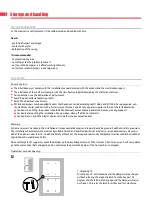
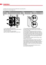
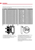
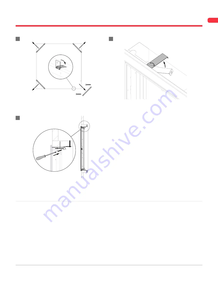
3. Set aside the screws that are affixed to one of the cross slats,
then unscrew the 4 cross slats of the mounting frame and fold
the 8 plates in the frame.
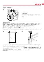
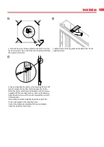
4. Rotate the four fastening plates on the damper 90° (to the
upright position).
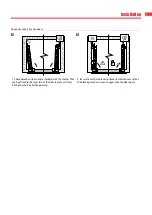
5. With the opening prepared the shutter can be handled
into position, from the room side. Ensure that the trailing lead
cables are not trapped at this stage and freely hang loose. Do
not distort or twist the frames as this will affect the correct
operation and sealing of the shutter. Check for squareness by
measuring the frame diagonals (they must measure the same).
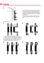
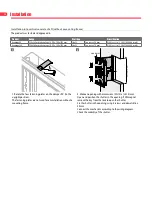
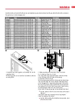
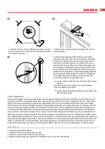
Fasten the shutter onto the mounting frame with the 4 screws sup-
plied with the mounting frame, as shown in the drawing. Tightening
the screws pulls the shutter towards the wall until its final position.
It also makes it possible to slightly correct the angle of the
shutter with respect to the mounting frame.
Caution: make sure that the screws don’t exceed the sleeve’s
thickness!
Connect the mechanism according to the wiring diagram.
Check the mobility of the shutter.
Caution: before putting the installation into operation, clean
off all the dust and dirt.
Product maintenance
Smoke control dampers must form part of a professionally designed Smoke and Heat Exhaust Ventilation System (SHEVS) that will
be specially suited to an individual buildings size, usage and structure. SHEVS are Fire Safety Installations and it is essential they are
subject to the routine inspection and maintenance requirements of the country of installation of the SHEV system. For example,
BS7346 part 8, NF S 61-933 and EN 13306. Avantage and Kamouflage DP dampers are virtually maintenance free, however, they will
require occasional operation and maintenance as part of a system specific routine operational test and maintenance procedure. It
is recommended that as part of the system testing and maintenance procedure that different individual dampers are operated at
each system test such that each damper within a system is inspected, checked and tested at least once in any 6-month period. The
following instructions are a general guide and our recommendations to the procedures required: a) Operate each ventilator at least
once; checking that the unit opens and closes fully. b) Visually observe the control mechanisms ensuring the devices are in place and
are not obviously damaged or obstructed. c) Inspect each ventilator in its open position to check that the intumescent fire seals and
smoke seals between the vent frame and doors are not damaged and are securely attached. Wipe any dirt build up from the seals.
Inspect the door leading and trailing edge seals and lightly lubricate with a machine oil and a silicone grease to the release latch.
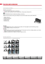
Maintenance
∎
No specific maintenance required.
∎
Schedule at least two running checks each year.
∎
Remove dust and all other particles before start-up.
∎
Follow the local maintenance regulations (i.e. BS9999 Annex V; NF S 61-933) and EN13306.
3
4
5


