19
Installation
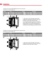
Installation into vertical shaft GLASROC F V500 with built-in mounting frame
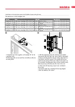
The product was tested and approved in:
Product
Range
Wall type
Classification
Kamouflage 60 MP
350x385 mm ≤ Kamouflage 1V MP ≤ 700x1075 mm Shaft
Glasroc F V500 ≥ 35 mm
EI 60 (v
ed
i
n
o) S 1500 C10000 AA multi
Kamouflage 120 MP
350x385 mm ≤ Kamouflage 1V MP ≤ 700x1075 mm Shaft
Glasroc F V500 ≥ 50 mm
EI 120 (v
ed
i
n
o) S 1500 C10000 AA multi
e
≥ 125 mm
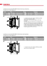
KAMOUFLAGE MP
EASY-KAP ME/MP
e
A = 2 x e + 20 mm
(W+
A
) x (H+
A
) mm
(W+
20) x (H+
20) mm
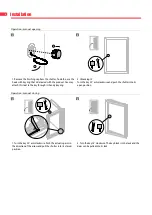
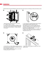
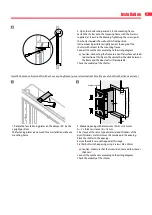
1. Put glue type GLASROC F V500 on the uprights and cross
pieces and between the lining and the wall. Screw the sleeve
using chipboard screws Ø5 x 70 mm at 150 mm intervals.
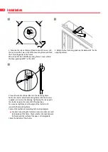
Two fixing lugs are provided at the bottom and at the top of
the mounting frame: fold these against the sleeve. First coat
the opening with glue GLASROC F V500. Glue the mounting
frame to the lining taking care not to misshape it. The finished
opening must have the same size as the mounting frame
(W+10) x (H+10) mm.
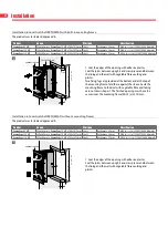
Installation into vertical shaft GLASROC F V500 (without a mounting frame)
The product was tested and approved in:
Product
Range
Wall type
Classification
Kamouflage 60 MP
350x385 mm ≤ Kamouflage 1V MP ≤ 700x1075 mm Shaft
Glasroc F V500 ≥ 35 mm
EI 60 (v
ed
i
n
o) S 1500 C10000 AA multi
Kamouflage 120 MP
350x385 mm ≤ Kamouflage 1V MP ≤ 700x1075 mm Shaft
Glasroc F V500 ≥ 50 mm
EI 120 (v
ed
i
n
o) S 1500 C10000 AA multi
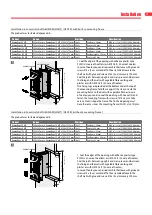
KAMOUFLAGE MP
e
≥ 125 mm
e
A = 2 x e + 10 mm
(W+
A
) x (H+
A
) mm
(W+10) x (H+10) mm
1. Put glue type GLASROC F V500 on the uprights and cross
pieces and between the lining and the wall. Screw the sleeve
using chipboard screws Ø5 x 70 mm at 150 mm intervals.
1
1

