background image


TX Pole User Manual


Page 

5

 of 

24


 Version 1 

 Status 

 ISSUED FOR USE 

Document Number 


PRJ-TXP-MAN-002


Table 2 

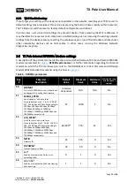
 Main connector pinout


PINOUT 

PIN  Name 

I/O  Description 


Main connector 

Front View 

ESP_TX0 

ESP transmit serial 0 

+V_PLUG 

Device external supply with priority over 
internal battery. 

ESP_RX0 

ESP receive serial 0 

GND 

Ground 

EXT_ON_N 

A  switch  can  be  connected  across 
EXT_ON_P and EXT_ON_N to turn on the 
device while mounted far up to a pole. 

EXT_ON_P 

ESP_EN_BOOT 

Connect to GND during power up to enter 
ESP bootloader.  

DIO3 

I/O 

GPIO pin 

 
Table 3 - Expansion connector pinout 

 Reserved for future models 

PINOUT 

PIN  Name 

I/O  Description 


Expansion connector 

Front view


RSVD1 

Reserved 

RSVD2 

Reserved 

RSVD3 

Reserved 

RSVD4 

Reserved 

RSVD5 

Reserved 

RSVD6 

Reserved 

RSVD7 

Reserved 

RSVD8 

Reserved 

RSVD9 

Reserved 

10 

RSVD10 

Reserved 

 
Table 4 - Power Supply Ratings 

Parameter  

Minimum 

Maximum 

Units 

Supply Voltage (+V_PLUG relative to GND) 

+9 

+16 

DC Plug Current Consumption (I _PLUG) 

0.12 

3* 

 
*Maximum current consumption occurs when internal modem constantly transmits, and internal battery is being charged. 


For further detail about power consumption depending on mode of operation, see section 5.1. 


Summary of Contents for RFD TX Pole

Page 1: ...PRJ TXP MAN 002 RFD TX Pole User Manual RFDesign Pty Ltd 7 1 Stockwell Place Archerfield QLD 4108 rfdesign com au ...

Page 2: ...iguration 8 2 2 1 Change Network Settings 8 2 2 2 TX Pole as a station 10 2 2 3 Wi Fi Troubleshooting 11 2 3 TX Pole Internal RFD900x Modem settings 11 2 3 1 Modifying parameters with the TX Pole web interface 14 2 4 Firmware Update 14 2 5 Vehicle Modem 16 3 Applications 18 3 1 Ground Control Station 18 4 Antenna Recommendation 19 5 Technical Specifications 20 5 1 Power Consumption 20 5 2 Modem Sp...

Page 3: ...TX Pole User Manual Page 2 of 24 Version 1 Status ISSUED FOR USE Document Number PRJ TXP MAN 002 Document revision history Version Date Changes 1 0 01 09 2020 Initial release ...

Page 4: ... The RFD TX Pole is a rugged data and control system for long term outdoor deployment Providing long range connection through RFD 900x long range modem the system can be used for functions ranging from messaging to sensor monitoring to equipment controls The wide range of supported input voltages and internal battery system accommodates a wide range of power solutions The heavy duty sealed enclosu...

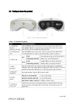
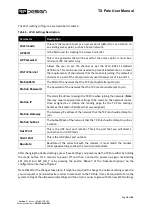
Page 5: ...g no Wi Fi connection Alternating with blue Battery low connected to Wi Fi Green Solid Healthy battery no Wi Fi connection Alternating with blue Healthy battery connected to Wi Fi 4 Main Connector External supply connector to power and or charge device Two different harnesses can be used depending on application Refer to section 7 for more information about the harnesses For connector pinout refer...

Page 6: ... power up to enter ESP bootloader 8 DIO3 I O GPIO pin Table 3 Expansion connector pinout Reserved for future models PINOUT PIN Name I O Description Expansion connector Front view 1 RSVD1 Reserved 2 RSVD2 Reserved 3 RSVD3 Reserved 4 RSVD4 Reserved 5 RSVD5 Reserved 6 RSVD6 Reserved 7 RSVD7 Reserved 8 RSVD8 Reserved 9 RSVD9 Reserved 10 RSVD10 Reserved Table 4 Power Supply Ratings Parameter Minimum Ma...

Page 7: ... EXT_ON_N and EXT_ON_P wires together on the power The system defaults to be a Wi Fi Access Point AP and self assigns the IP 192 168 4 1 Use your computer or smart device to search for and connect to the access point Wi Fi network generated by the TX Pole SSID TXPOLE XX XX XX Password txpole123 by default It may be necessary to disable mobile data on tablets and phones to force the browser to use ...

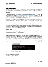
Page 8: ...hrough the steps to get your module ready to use Figure 3 First run wizard To complete the wizard the remote modem on the aircraft should be powered up have the same firmware version and be bound to the TX Pole If the remote RFD900x modem is the one supplied along the TX Pole both devices are ready to proceed If it is not refer to section 2 5 to flash on the Figure 2 Configuration homepage ...

Page 9: ...t case press the button on the TX Pole 5 times rapidly to reset default values After that the wizard can be reengaged Follow on screen instructions and once the wizard is successfully completed your device is ready to be used and further configuration is optional 2 2 Wi Fi Configuration It is strongly recommended to change the default Wi Fi settings to ensure the security of the radio link and ove...

Page 10: ...quire appropriate settings to be made on the network router Once assigned as a station the landing page for the TX Pole settings becomes the Station IP address that was assigned Station Gateway The Gateway IP address of the network that the TX Pole should attempt to join Station Subnet The Subnet Mask of the network that the TX Pole should attempt to join as a station Host Port This is the UDP hos...

Page 11: ...he name specified on StationSSID in the previous step On your device open a Chrome based browser and enter the following address http TXPOLE XX XX XX local where the Xs are the same as the Xs in the access point network name Analogously on Android download Bonjour Browser app to find and access to the TX Pole IP address Advanced users The module must be set up by choosing Station in Wi Fi Mode set...

Page 12: ...rameters For further information regarding the internal modem on which the TX Pole is based on refer to the RFD900x Peer to Peer Firmware and RFDesign Modem 900x Datasheet documents using the links in section 6 Table 6 RFD900x parameters Reg S Register Description Default Value Maximum Value Minimum Value Must be the same at both ends of the link S0 FORMAT This is for EEPROM version it should not ...

Page 13: ...Yes S13 RTSCTS Ready to send and Clear to send flow control 0 1 0 No S14 Max Window Max transit window size used to limit max time latency if required otherwise will be set automatically 131 400 20 Yes S15 Encryption Level Encryption level 0 off 1 128bit AES 0 1 0 Yes S16 GPIO1 1 R C input Set GPIO 1 1 pin 15 as R C PPM input 0 1 0 No S17 GPIO1 1 R C output Set GPIO 1 1 pin 15 as R C PPM output 0 ...

Page 14: ...ier this is based on RSSI figures After v3 12 this changes to being based on receiver dBm 50 158 20 28 50 58 No Notes 1 The listed values are the full range of options available on unrestricted modems The range of settings available may be altered on compliant systems to maintain compliance to the appropriate standards 2 ECC Software Detection and correction extra packet information twice the pack...

Page 15: ...igure 6 T Pole modem configuration page Settings can be refreshed using the Load Fresh parameters button Parameters can be adjusted in the text boxes as required and then applied by means of the Save parameters button Changes on the AIR_SPEED NETID TXPOWER MIN_FREQ MAX_FREQ and NUM_CHANNELS parameters should be applied to remote radio settings as well to avoid losing the radio link 2 4 Firmware Up...

Page 16: ... new SPIFFS is uploaded you will be required to reboot your TX Pole The subsequent bootup might also update the internal radio firmware For that reason ensure you have no other RFD900x or RFD900ux modems on at the same time and allow up to 10 minutes for the device to bootup completely Figure 7 Update page ...

Page 17: ...e parameters as the modem on the TX Pole to ensure a proper communication link To do so an FTDI cable a jumper and the RFD900 tools or a serial terminal program are needed Connect the FTDI cable and the jumper as per figure 8 or 9 depending on the remote modem model The black wire of the FTDI i e pin 1 should connect to pin 1 on the modem and the jumper should connect pins 2 and 3 on the top row t...

Page 18: ...I cable the vehicle modem will appear as local If these parameters have been not modified on the TX Pole side or they have been reset to default values by pressing the button 5 times rapidly the easiest way to configure them on the remote modem is by pressing Reset to Defaults button Another important step is to set modem GPIO1 1 as a PPM output This allows the modem pin 15 to output the PPM strea...

Page 19: ...le is configured as described throughout section 2 connect your computer or smart device to the configured Wi Fi network that is either the TX Pole Access Point or the linked network when using the module as a station Then open Mission Planner on your computer or Tower App on your Android device and choose TCP or UDP and press the button CONNECT as per figure 11 Parameters should start loading pro...

Page 20: ...ely can be used however the ones supplied along with the TX Pole and shown in figure 13 are recommended for almost every application For other antenna options visit our store at http store rfdesign com au Figure 13 a 900MHz 3dBi Half Wave Dipole Antenna RPSMA b Antenna 2 4GHz 5dBi Dipole RPSMA Any of the two 900 MHz antennas can be left unmounted if antenna diversity is not to be used For further ...

Page 21: ...external power supply of 9V to 16V is needed and must be able to supply at least 2A If additionally the device is to be used while charging the power supply must supply the nominal current consumption For this reason a power supply of 9V to 16V and 3A is recommended 5 2 Modem Specification Table 8 Performance Supported RF Data Rates 4 64 125 250 and 500 Kbps Indoor Range 500 m 1 km Line Of Sight R...

Page 22: ... Parameters Condition Min Typical Max Unit Input Frequency 2412 2484 MHz Output Impedance 50 Ω Tx Power 11n MCS7 12 13 14 dBm 11b mode 17 5 18 5 20 dBm Sensitivity 11b 1 Mbps 98 dBm 11b 11 Mbps 89 dBm 11g 6 Mbps 92 dBm 11g 54 Mbps 74 dBm 11n HT20 MCS0 91 dBm 11n HT20 MCS7 71 dBm 11n HT40 MCS0 89 dBm 11n HT40 MCS7 69 dBm Adjacent Channel Rejection 11g 6 Mbps 31 dB 11g 54 Mbps 14 dB 11n HT20 MCS0 31...

Page 23: ... Number PRJ TXP MAN 002 5 5 Ordering Guide Order code Description TXPOLE 900 TX Pole unlocked region 902 928MHz TXPOLE 868 TX Pole unlocked region 865 870MHz TXP HRN 01 External Mast Power Harness 5m 5 6 Physical Dimensions Figure 14 TX Pole physical dimensions in millimeters ...

Page 24: ...nts RFD900x 20DataSheet pdf Firmware http files rfdesign com au firmware Peer to Peer firmware User Manual http files rfdesign com au Files documents RFD900x 20Peer to peer 20User 20Manual 20V1 1 pdf RFDesign Programming Tools Software http files rfdesign com au tools Manual http files rfdesign com au Files documents RFD 20Modem 20Tools 20Manual 20V1 1 pdf Mission Planner http ardupilot org planne...

Page 25: ...NOUT PIN Name Wire colour Description Main connector Front view 1 NC Not connected 2 V_PLUG Red Device external supply with priority over internal battery 3 NC Not connected 4 GND Blue Ground 5 EXT_ON_N Green A switch can be connected across EXT_ON_P and EXT_ON_N to switch on and off TX Pole when connected far up to a pole 6 EXT_ON_P Yellow 7 NC Not connected 8 NC Not connected ...

Reviews: