RFDMX User Manual
Page
3
of
12
–
Version 1.3
–
Status
–
DRAFT
Document Number
–
PRJ-TXP-MAN-001
2.
Overview
2.1
Features
•
Support to up to 512 DMX channels
•
Same hardware can operate as transmitter or receiver
•
Secure link between transmitter and receiver nodes
•
One-off synchronization process
•
Long-range resilient wireless communications
•
On board LED driver (optional)
•
DIP switch network and DMX address setup
2.2
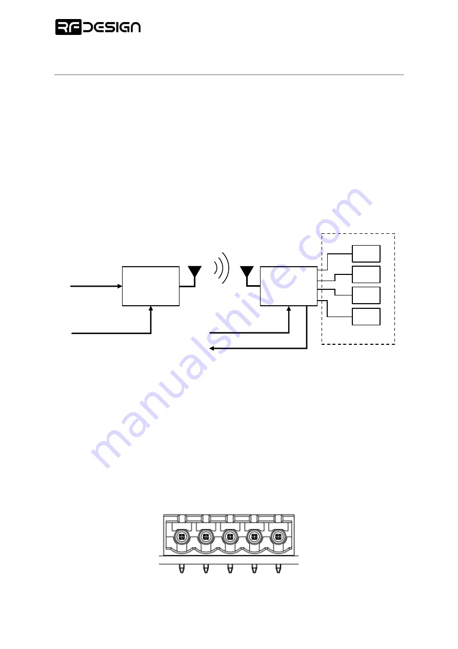
Functional diagram
2.3
Connector Pinouts
The RFDMX features a power and communications connector and a LED driver output connector. If
the device is set to transmitter, power and DMX input are mandatory connections. If operating as
receivers only power is required. In Transmitter mode the TX/RX- and TX/RX+ pins are DMX stream
inputs to the RFDMX board and in Receiver mode, the TX/RX pins are DMX stream outputs.
D
M
X
B
/D
-
D
M
X
A/
D
+
D
M
X
GN
D
P
OW
ER
GN
D
P
OW
ER
V
IN
Power and DMX connector front view
LED
LED
LED
LED
DMX IN
RFDMX
TX
EXTERNAL POWER
SOURCE
RFDMX
RX
Optional
DMX OUT
EXTERNAL POWER
SOURCE


