Configuration
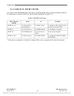
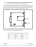
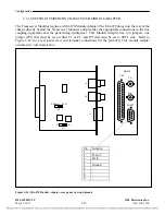
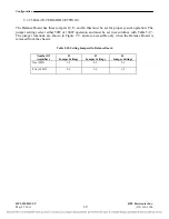
Table 5-11. Voltage control jumper settings on module adapter Input Board
I/O Adapter Module
part number
I/O Adapter Module type
J4 and J5 jumper position
105770-2
105770-4
2 function 48/125V solid state
4 function 48/125V solid state
48V position
for 48V operation,
105740-2
2 function 48/125V relay
4 function 48/125V relay
125V position
for 125V operation
105740-4
105770-3
2 function 250V solid state
105770-5
4 function 250V solid state
125V position
105740-3
2 function 250V relay
for 250V operation
105740-5
4 function 250V relay
5.3.1.6
SETTING JUMPERS ON THE TELEPROTECTION TRANSCEIVER MODULE
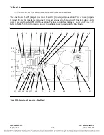
The Transceiver Module has several jumpers that must be set for proper system operation. All of these
jumpers are set at the factory and should not be changed by the user. In addition to this, all test points
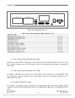
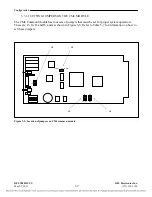
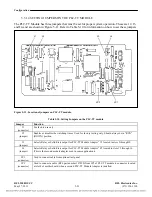
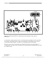
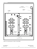
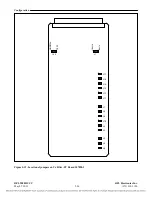
are for factory use only. The Transceiver Module has 5 LEDs as follows: D1 through D5. The location
of these LEDs is shown in Figure 5-13. The function of the LEDs is shown in Table 5-12.
D1
D2
D3
D4
D5
Figure 5-14. Location of LEDs on Transceiver module.
RFL 9508D UCC
RFL Electronics Inc.
May 27, 2011
5-23
(973) 334-3100


