Configuration
5.3.1.7
SETTING JUMPERS ON THE DIGITAL TRANSCEIVER MODULE
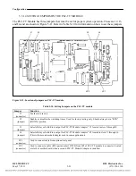
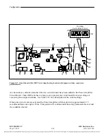
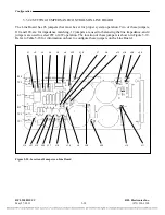
The digital transceiver is quite similar to the teleprotection transceiver; the components placement is
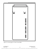
the same, and also the jumper placement and LEDs as shown in figure 5-13 is the same. All of the
jumpers are set at the factory for proper system operation, and should not be changed by the user. In
addition to this, all test points are for factory use only. The Transceiver Module has 5 LEDs as follows:
D1 through D5. The location of these LEDs is shown in Figure 5-13. The function of the LEDs is
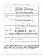
shown in Table 5-13
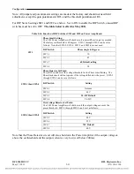
Table 5-13. Function of LEDs on the Transceiver module
LED
Function
D1 Link
status
Has two states as follows:
GREEN: Digital link is established
Flashing RED: The transceivers are in training process.
D2
Presently unused, normally GREEN (LED is ON when power is applied to transceiver module)
D3
Presently unused, normally GREEN (LED is ON when power is applied to transceiver module)
D4 Boot
Status
Has two states as follows:
RED: The transceiver is booting
OFF: The Transceiver is operating and running.
D5 Power
LED
GREEN when transceiver module power is ON
RFL 9508D UCC
RFL Electronics Inc.
May 27, 2011
5-25
(973) 334-3100

