Configuration
5.3.2.2
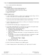
SETTING JUMPERS ON TX FILTER AND TX FILTER TUNING
The Tx Filter consists of two PC boards that are mounted at right angles to each other and are
supported by an aluminum frame. The Tx Filter has a total of 44 jumpers that must be configured for
proper system operation. Two of these jumpers (J1 and J45) are used to select the bandwidth of the
filter which can be either 8kHz or 16kHz. Jumper J44 is used for system testing, and the other 41
jumpers are used to tune the center frequency of the filter from 24kHz to 496kHz. The outer edges are
20kHz and 500kHz. Tuning the filter is done from the RF Section of the NMS software.
NOTE
For single 4kHz or single/dual 2.5kHz operation, set this filter to 8kHz wide.
For more channels, set it to 16kHz wide.
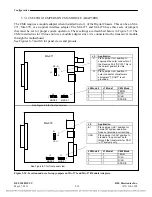
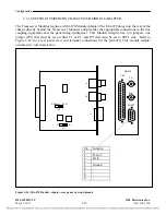
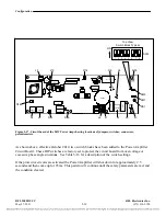
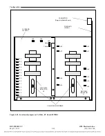
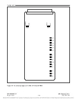
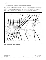
27 of the jumpers are located on the 107828-2 board. This is the board with the two large air core
inductors. The location of these jumpers is shown in Figure 5-17. The remaining 17 Jumpers are
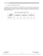
located on the 107828-1 board. The location of these jumpers is shown in Figure 5-18. Refer to Table
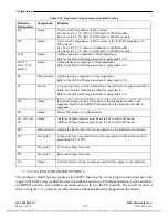
5-16 for information on how to configure the jumpers on the Tx Filter.
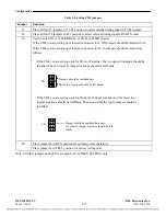
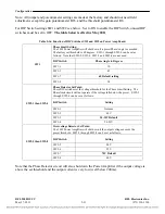
Table 5-17. Tx Filter Setup Jumpers
Jumper
Function
J1 and J45
Used to select 8kHz or 16kHz Tx Filter bandwidth.
Both jumpers must be set to 8kHz to select 8kHz bandwidth.
Both jumpers must be set to 16kHz to select 16kHz bandwidth.
J44
Used to select Normal or Test operation.
Set to Normal position for normal system operation.
Set to Test position to move the T1 Test Point from one coil to another during
system testing. Used for tuning the air core inductors L1 and l2.
J1 to J13, and
Used to tune the center frequency of the Tx Filter from 24kHz to 496kHz. The
outer edges are 20kHz and 500kHz. Tuning the filter is done from the RF
section of the NMS software.
J15 to J43
For example, for a center frequency of 90kHz, the following jumpers should be
installed: J3, 5, 6, 8, 10, 11, 18, 20, 23, 24, 34, 35, 37 and 38
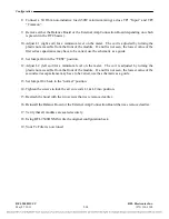
Be sure to loosen the inductor fixing screws before making an adjustment, and to tighten them after the
adjustment is completed.
RFL 9508D UCC
RFL Electronics Inc.
May 27, 2011
5-32
(973) 334-3100

