Configuration
5.3.2.6.1
RX FILTER TUNING PROCEDURE
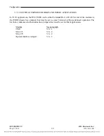
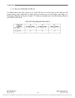
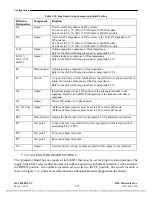
Table 5-20 Filter Parameters
8kHz Bandwidth
16kHz Bandwidth
Attenuation at +/- 4Khz<0.35 dB
Attenuation at +/- 8Khz<0.35 dB
Attenuation at +/- 12Khz>9.5 dB
Attenuation at +/- 18Khz>9.5 dB
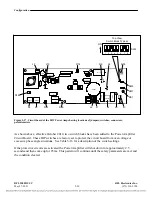
Useful tips:
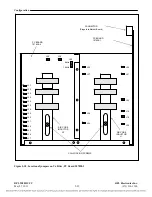
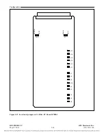
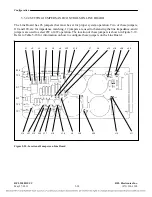
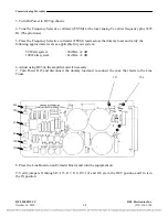
L2 controls the balance of the filter (flat response at both sides of center frequency)
L1 controls the attenuation at the upper side of center frequency.
L3 controls the attenuation at the lower side of center frequency.
WARNING
The adjusters are very easy to break, take care when turning.
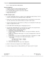
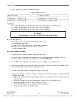
Required Equipment:
Frequency Selective Voltmeter with high impedance input
50 Ohm non-inductive load
PC with 9508D NMS, and RS-232 9-pin female connection
Phillips head core alignment tool for L1, L2, and L3
9508 RF Extender Card
RX Filter Tuning Procedure:
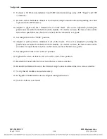
1.
Turn Power OFF to the RF and AF Chassis of the 9508D.
2.
Use RFL 9508D NMS software to generate a list of appropriate jumper settings. Refer to
Section 4 of the manual for more information on RFL 9508D NMS.
3.
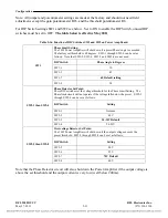
Set the RX Filter jumpers for Center Frequency according to your configuration.
4.
Disconnect the BNC cable from the MA-470 Rx input. With the same cable terminate the RF
chassis’s RX output into a 50 ohm non-inductive load.
5.
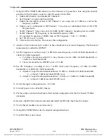
Connect a frequency selective voltmeter (FSVM) to the load.
6.
Arrange a loopback connection between Transmitter TX OUT and Receive Filter RX IN
following these steps.
a.
Bypass the Transmit Filter by placing J44 on the rear of the filter to the “Test” position and
removing J45.
b.
Place the loopback switch on the Attenuator Module for the Test position (UP).
c.
On the Line Board set J25 to “Loop” and J23 to “4W”.
d.
Place RX Filter Board on an extender card for adjustment.
e.
Turn power ON to the AF & RF Chassis.
RFL 9508D UCC
RFL Electronics Inc.
May 27, 2011
5-41
(973) 334-3100

