Commissioning Procedure
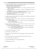
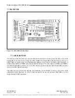
10. Using a FSVM, monitor the local Tx carrier frequency plus 3825 Hz at TP7 (-) and TP6 (+).
11. Adjust switch S1, Resistor R1 and Inductor L1 for a minimum reading on the FSVM.
12. Reposition jumpers J1 through J9 IN until a combination of capacitance provides a minimum
reading on the FSVM.
13. Reposition jumpers J15, J17, J18, J19, J21, and J22 IN until a combination of inductance provides
a minimum reading on the FSVM.
14. Repeat steps 11 above until lowest level is attained.
15. Repeat steps 1 to 15 in Section 6 for opposite 9508D end.
6.2.5.2
ADJUSTING THE RECEIVER LEVEL
1. Using a FSVM, monitor the local Rx carrier frequency plus the pilot frequency (normally 3825 Hz)
at RX OUT connector from RF to AF chassis – Terminate the connection on a 50 ohm dummy load.
2. Adjust Rx level potentiometer R10 for a pilot level of –20 dBm.
3. Turn equipment off, remove extender card and re-install Line Board in the chassis
4. Return NMS settings to match those on the RFL parameters file.
5. Test all system functions.
RFL 9508D UCC
RFL Electronics Inc.
October 14, 2010
6-6
(973) 334-3100

