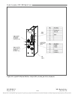
Module Descriptions, RFL 9508D Digital Section
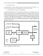
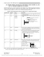
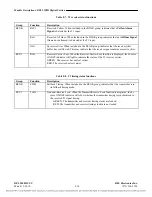
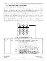
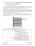
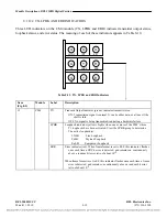
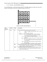
Table 8-2. System status indicators and the ACO switch
Item
(Fig. 8-5)
Module Module
Label
Multiplexer
Front Panel
Label
Description
1 Power
supply
PS
- - -
Power Supply Module Fail LED. Lights when power
supply module has failed.
2 Power
supply
PWR
POWER
Power LED. Lights when the 9508D is powered. If the
9508D is equipped with a redundant power supply,
this indicator will remain on if one of the power
supplies has failed and the remaining supply has
enough capacity to power the 9508D by itself.
3 Power
supply
DIS/EN
- - -
Alarm Cut-Off Switch (Disable/Enable). When this
switch is in the Disabled position and no alarms are
active, the alert indicator will light. When this switch
is in the Enabled position the ALERT and ALARM
relays are on line and will activate in response to
system fault conditions.
NOTE: If the 9508D contains two power supply
modules, the ACO switches on both power supply
modules must be placed in the DIS position to disable
the ALERT and FAIL relays.
4 Power
supply
NORM
NORMAL
Normal LED. Lights when neither an ALERT or an
ALARM condition exists.
5 Power
supply
ALERT
ALERT
Alert LED. Lights when one or more of the following
conditions exists: (1)
EXCESSIVELY LOW RECEIVE SIGNAL (RX IN
indicator off)
REC YELLOW ALARM (RX IN indicator blinking)
LOOPBACK ACTIVATED (LPBK indicator on)
FALLBACK TIMING ACTIVATED (The TIMING
indicator for the programmed timing mode will be
blinking)
SINGLE POWER SUPPLY FAILURE (when two
power supplies are installed)
ACO ON
6 Power
supply
FAIL
ALARM
Fail LED. Lights when one or more of the following
conditions exists: (2)
CPU FAILED (CPU indicator on)
SIGNAL PRESENT BUT OUT-OF-FRAME (RX IN
and FRM indicators on)
NO TRANSMIT OUTPUT (TX OUT indicator off)
1.
An unframed "all ones" is an E1 Alarm Indication Signal (AIS).
2.
This indicator also lights briefly at power-on.
RFL 9508D UCC
RFL Electronics Inc.
March 11, 2010
8-9
(973) 334-3100

