Module Descriptions, RFL 9508D Digital Section
8.1.12
8.1.12.1
FRONT PANEL LED INDICATORS
LOOP, INT AND EXT INDICATORS
The CM4 timing source selected by the user is called the
primary
timing source. Common modules
set up for External, Looped, or Through timing also have a
fallback
timing mode. Upon loss of
primary timing, they undergo a smooth, carefully controlled switch to Internal timing.
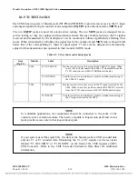
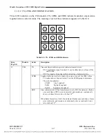
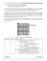
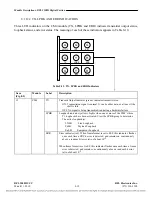
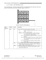
Three LED indicators on the CM4 (LOOP, INT, and EXT) indicate the current T1 transmitter timing
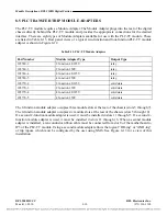
configuration. Table 8-9 explains the function of each of these indicators. If the CM4 is in its fallback
timing mode, one of these three indicators will be on, while another will be blinking. The blinking
indicator shows the primary timing mode set by the user. The indicator that is on continuously
indicates the fallback timing mode, which is now in effect.
The meaning of the LOOP indicator depends on the multiplexer type. In terminal multiplexers, the
LOOP indicator indicates loop timing. In drop/insert multiplexers, the LOOP indicator indicates
through (THRU) timing.
RFL 9508D UCC
RFL Electronics Inc.
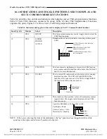
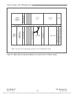
Table 8-11. Loop, Internal and External Indicators
Item (Fig. 8-5)
Module
Label
Description
15
CM4
LOOP
Loop or Through Timing Mode indicator (green). Its actions
will depend upon the multiplexer configuration:
Terminal Multiplexers:
ON: The CM4 transmitter is loop timed.
BLINKING: Loop is the primary timing mode, but the CM4
module is currently in fallback timing mode.
Drop/Insert Multiplexers:
ON: The CM4 transmitter is through timed.
BLINKING: Thru is the primary timing mode, but the CM4
module is currently in fallback timing mode.
INT
Internal Timing Mode indicator (green). Lights when the CM4
E1 transmitter is internally timed.
EXT
External Timing Mode indicator (green). Lights when the CM4
E1 transmitter is externally timed. Blinks when EXT is the primary
timing mode, but the CM4 module is in fallback timing mode.
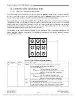
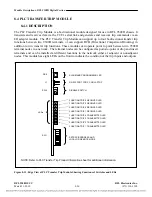
G G G
LOOP INT EXT
G Y R
TX LPBK ERR
G Y R
RX BPV FRM
March 11, 2010
8-18
(973) 334-3100

