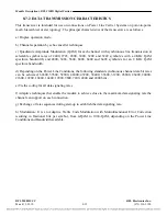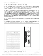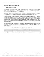
Module Descriptions, RFL 9508D Digital Section
8.10.2
SPECIFICATIONS
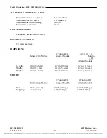
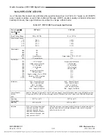
As of the date this manual was published, the specifications shown in Table 8-17 apply to all 2000 PS
power supply modules, except where indicated. Because all RFL products undergo constant refinement
and improvement, these specifications are subject to change without notice.
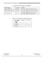
Table 8-17. IMUX 2000 Power Supply Specifications
Power Supply
→
Specifications
↓
9547-840 9547-965
Input Voltage Range
200 to 300 Vdc
38 to 150 Vdc
Max Output Current:
+5V
+15V
-15V
-48V
5.00A
0.75A
0.75A
0.10A
6.00A
1.75A
1.00A
0.10A
Adjustments:
R44
R49
R50
R61
R76
NA
NA
NA
Output adjust
+5V output adjust
NA
NA
NA
Output 5V/+15V/-15V
NA
Test Points:
TP1
TP2
TP3
TP4
TP5
TP6
TP7
TP8
TP9
TP10
+15 Volt output
Output circuit common
+5Volt output
+15 Volt output
Output circuit common
-15 Volt output
+5 Volt output
NA
-15 Volt output
-48Vdc output
NA
NA
NA
NA
Input circuit common
FET gate drive
Supply voltage (Vcc) to PWM
Input to +15Vdc regulator
-48Vdc output
NA
Indicators
DS1 – Normal (Green)
DS1 – Normal (Green)
DS2 – Alert (Yellow)
DS2 – Alert (Yellow)
DS3 – Fail (Red)
DS3 – Fail (Red)
DS4 – Power (Green)
DS4 – Power (Green)
DS5 – Supply Fail (Red)
DS5 – Supply Fail (Red)
Alarm Disable
Switch
Enables “dropout” of relays K51 & K52 on Power Supply Alarm I/O module when in the ENABLE position.
Keeps relays K51 & K52 on Power Supply Alarm I/O module “pulled in” when in the DISABLED position.
SW1
-20
o
C to +65
o
C
-20
o
C to +65
o
C
Operating
Temperature
95% @ +40
o
C
95% @ +40
o
C
Humidity
Isolation
2500 Vdc isolation from input
terminals to ground, output
terminals to ground, input
terminals to output terminals,
relay contacts to ground, and
relay contacts to coil.
2500 Vdc isolation from input terminals to ground, output terminals to
ground, input terminals to output terminals, relay contacts to ground,
and relay contacts to coil.
RFL 9508D UCC
RFL Electronics Inc.
March 11, 2010
8-39
(973) 334-3100

