RFL 9508 PLC-TT
RFL Electronics Inc.
September 5, 2012
9
(973) 334-3100
5.
Insert the I/O Adapter Module into the rear of the shelf directly behind the module
slot where the PLC-TT will be installed.
The I/O Adapter Module will take up three slots for the 2 function version,
and six slots for the 4 function version. This must be taken into
consideration when selecting module slots.
6.
Connect all signal wiring to the rear panel of the I/O Adapter Module.
7.
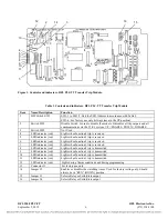
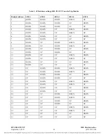
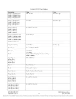
Using DIP switches SW1-1 to SW1-5, set the PLC-TT module address.
For remote access, each channel module in a 9508 chassis must have a
distinct module address. For this module, valid module addresses are the
numbers “1” to “31”, using the code shown in Table 3. The module address
is usually set to the number of the physical slot in the shelf that the module
will occupy; it can be set to any number from 1 to 31 that is not already
being used by another module in the same 9508 chassis.
8.
Check the setting of DIP switch SW1-6.
This switch is for factory use only and should always be set to the UP position.
9.
Set toggle switch SW2 to the DOWN position to disable the module.
10.
Check the setting of jumper J2. It should be in the RUN position. This will enable the
watchdog timer.
11.
Check the setting of jumper J3. It should be in RELAY position if the I/O Adapter
Module has a relay output. It should be in SOLID STATE position if the I/O Adapter
Module has a solid state output.
12.
Slide the module into the selected module slot until it is firmly seated.
13.
Program the module parameters using local or remote interface as applicable.
14.
Turn service on by placing the SW2 toggle switch to the UP position.
15.
On the module record card (located to the right of the shelf), record the time slot number
and other pertinent information.
The RFL PLC-TT module is now installed.

