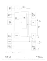
Figure 6. Directional Comparison Blocking, block diagram
The PLC-TT module retains all of its existing functionality and operates in DCB mode only if
commanded to. Otherwise the four functions operate as independent transfer trip commands. DCB
mode is invoked by setting P13 bit 6 to a 1. This can be done directly or via NMS.
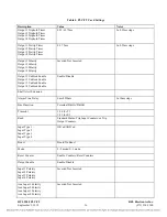
Once in DCB mode the meaning of P7 bit 0 and P7 bit 1 change. In normal mode these bits set the
polarity of outputs 1 and 2. In DCB mode P7 bit 0 now selects the polarity of the start input and P7 bit
1 selects the polarity of the stop input. Both polarities are normal if the bit is a zero and inverted if the
bit is a one. To set these bits in NMS one should select “output polarity” for output 1 or 2 and change it
appropriately.
ALERTS AND ALARMS
If there is a loss of signal, or if the disable switch is down, the transfer trip module will issue a module
alert signal to the shelf common module.
ZONE EXTENSION FUNCTION
The zone extension feature allows an indefinitely-long trip to be transferred over PLC, even though the
internal 2-second timeout prevents long signaling. Only function 1 (input 1 /output 1) is affected by
this function.
A continuously-active input generates periodic codes (code-2) that maintain the active output at the
receiver. The activate code is sent for approximately 400 ms and is repeated based on the repetition
(extension) timer (1-126 minutes). Once the output is active, it remains active until either the
deactivation code is received or a sufficiently long time occurs without receiving another activation
code. The timeout for not seeing the activation code is twice the repetition rate. (2-246 minutes)
RFL 9508 PLC-TT
RFL Electronics Inc.
September 5, 2012
14
(973) 334-3100

