RFL Network Management Software
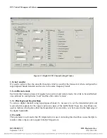
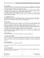
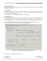
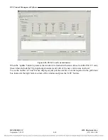
3. Tx Frequency
This pull down box sets the receive band’s lower edge frequency of the teleprotection channel. The
teleprotection channel is always 4 KHz wide; therefore this TX frequency should be set consistently
according with the Digital Channel Tx Frequency. For example:
If the digital channel Tx stream occupies a bandwidth from 92 KHz to 100 KHz (8 KHz Bandwidth),
the Digital channel Tx Frequency is set to 92 KHz and the teleprotection channel Tx frequency is set to
96 KHz, thus coinciding the upper edges of both frequency bands (100KHz).
If the digital channel occupies a bandwidth of 4 KHz, let’s say from 212 KHz to 216 KHz, both, the
digital channel and teleprotection channel Tx frequencies are set to 212 KHz, thus coinciding the upper
edges of both frequency bands.
4. Tx Signalling Frequency
Through this pull down box, three signaling frequencies are available for selection: 3825 Hz, 3600 Hz
and 2325 Hz. For 4 and 8 KHz operation, 3825 Hz should be selected; 2325Hz is for 2.5 kHz channel
operation. This setting selects the center frequency of the signaling band.
5. Rx Frequency
Through this pull down box you can select the receive band’s lower edge frequency of the
teleprotection channel. The teleprotection channel is always 4 KHz wide; therefore this RX frequency
should be set consistently according with the Digital Channel RX Frequency. For example:
If the digital channel Rx stream occupies a bandwidth from 192 KHz to 200 KHz (8 KHz Bandwidth),
the Digital channel Rx Frequency is set to 192 KHz and the teleprotection channel Rx frequency is set
to 200 KHz, thus coinciding the upper edges of both frequency bands (200 KHz).
If the digital channel occupies a bandwidth of 4 KHz, let’s say from 212 KHz to 216 KHz, both, the
digital channel and teleprotection channel Tx frequencies are set to 212 KHz, thus coinciding the upper
edges of both frequency bands.
6. F6 TX Att level
This is a digital attenuator which controls the output level of the analog transceiver.
7. Channel Control Register
Selects Tx and Rx on either USB (Upper Side Band) or LSB (Lower Side Band) of the pilot and
teleprotection commands. Transmission and reception can be configured the same or different (USB
in a given direction and LSB in the opposite direction) depending on the channel configuration
required.
8. F6 Teleprotection
Check to enable the PLC-TT Teleprotection Module.
At the bottom of the window there are four buttons similar to those present at the common tab: these
buttons are:
1. Write Teleprotection
This button is used to start a write operation of all the parameters in the Common and Digital channel
tabs to the Teleprotection transceiver.
RFL 9508D UCC
RFL Electronics Inc.
September 7, 2012
4-18
(973) 334-3100

