Configuration
5.2.1.8
5.2.1.9
5.2.1.10
5.2.1.11
5.2.1.12
5.2.2
TEST PANEL
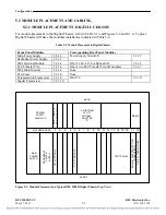
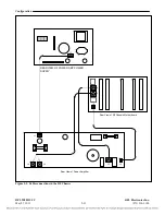
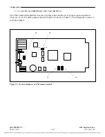
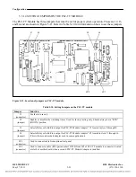
The Test Panel is an optional module that can be installed in slots 14 through 16. It has a cable which plugs
into JP1 of the PLC-TT Module. The Test Panel is used to test the Transfer Trip function.
TELEPROTECTION TRANSCEIVER
The Digital Chassis requires two Transceiver Modules. One of them is the teleprotection transceiver
which manages the F6 modulation for the teleprotection when included in the system, this module
must be mounted at the front of the chassis in slot 17.
DIGITAL TRANSCEIVER
The Digital Transceiver performs the QAM modulation, this module must be mounted at the front of
the chassis in slot 18.
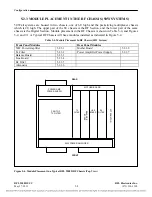
TRANSCEIVER MODULE ADAPTER
The Transceiver module requires a Module Adapter. The Module Adapter used with the Transceiver
Modules is the MA-470, which is mounted at the rear of the chassis directly behind the Transceiver
Modules.
DROP & INSERT APPLICATIONS
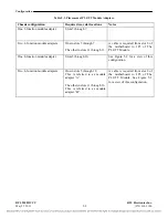
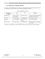
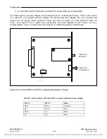
In Drop and Insert applications the Digital Chassis will have two CM4s installed, one in slot 10 and another
in slot 1. The CM4 in slot 10 is for Terminal End or Drop and Insert A (DI-A), and the CM4 in slot 1 is for
Drop and Insert B (DI-B). The CM4 in slot 10 has jumpers at location J6 that must be installed to select
either Terminal or DI-A, or DI-B. Refer to Figure 5-8 and Table 5-7 for instructions on how to set the J6
jumpers.
CABLING IN DIGITAL CHASSIS
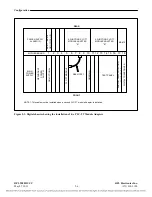
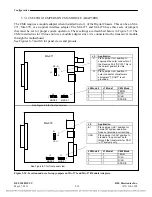
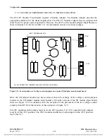
In most RFL 9508 installations there will be no cables inside the Digital Chassis. The only time a cable
will be installed in the Digital Chassis is when two PLC-TT Transfer Trip module adapters are
installed at the rear of the chassis. In this case, a small cable is installed from slot 8 of the mother board
to JP3 of the PLC-TT Transfer Trip module. The location of this cable can be seen in Figure 5-3.
RFL 9508D UCC
RFL Electronics Inc.
May 27, 2011
5-7
(973) 334-3100

